Lmr master™ s412e specifications, Vna performance capabilities – Atec Anritsu-S412E User Manual
Page 6
Page 7 of 28
LMR Master™ S412E Specifications
VNA Performance Capabilities
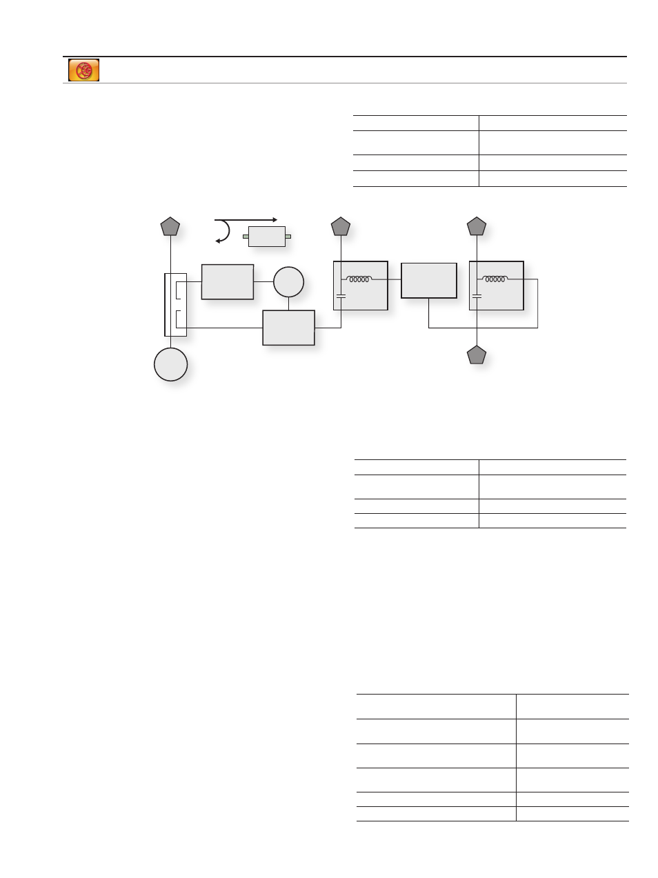
Bias Tee (Option 0010)
For tower mounted amplifier tests, the S412E with optional
internal bias tees can supply both DC and RF signals on the
center conductor of the cable during measurements. For
frequency sweeps in excess of 2 MHz, the LMR Master can
supply internal voltage control from +12 to +32 V in 0.1 V
steps up to 450 mA. Bias is available on VNA Port 2 and the
SPA Input (RF In).
Frequency Range
2 MHz to 4/6 GHz at VNA Port 2
Internal Voltage/Current
+12 V to +32 V at 450 mA.
Steady state
Internal Resolution
0.1 V
Bias Tee Selections
Internal, Off
DUT
Receiver
Port 1
Reference
Receiver
Port 2
Port 1
Bridge/Coupler
Source
LO
S
11
S
21
Internal
Bias Tee
SPA Input
SPA
Internal
Bias Tee
Internal Bias
+12 to +32 V
450 mA Max
The Compact LMR Master offers optional integrated bias tee for supplying DC plus RF to the DUT as shown in this simplified block diagram.
Vector Voltmeter (Option 0015)
A phased array system relies on phase matched cables
for nominal performance. For this class of application, the
LMR Master offers this special software mode to simplify
phase matching cables at a single frequency. The similarity
between the popular vector voltmeter and this software
mode ensures minimal training is required to phase match
cables. Operation is as simple as configuring the display for
absolute or relative measurements. The easy-to-read large
fonts show either reflection or transmission measurements
using impedance, magnitude, or VSWR readouts. For
instrument landing system (ILS) or VHF Omni-directional
Range (VOR) applications, a table view improves operator
efficiency when phase matching up to twelve cables.
The S412E solution is superior because the signal source
is included internally, precluding the need for an external
signal generator.
Distance Domain (Option 0501)
Distance-to-Fault Analysis is a powerful field test tool to
analyze cables for faults, including minor discontinuities
that may occur due to a loose connection, corrosion,
or other aging effects. By using Frequency Domain
Reflectometry (FDR), the Compact VNA Master exploits a
user-specified band of full power operational frequencies
(instead of DC pulses from TDR approaches) to more
precisely identify discontinuities. The Compact VNA Master
converts S-parameters from frequency domain into
distance domain on the horizontal display axis, using a
mathematical computation called Inverse Fourier Transform.
Connect a reflection at the opposite end of the cable and
the discontinuities appear versus distance to reveal any
potential maintenance issues. When access to both ends of
the cable is convenient, a similar distance domain analysis
is available on transmission measurements.
Option 0501 Distance Domain will improve your productivity
with displays of the cable in terms of discontinuities versus
distance. This readout can then be compared against
previous measurements (from stored data) to determine
whether any degradations have occurred since installation
(or the last maintenance activity). More importantly, you
will know precisely where to go to fix the problem and
minimize or prevent downtime of the system.
Option 0501 Distance Domain also supports field
measurements for optical fiber diagnostics. Anritsu Model
ODTF-1 test module works directly with RF techniques and
converts optical DTF signals to display on the VNA Master.
CW Frequency Range
2 MHz to 6 GHz
Measurement Display
CW, Table (Twelve Entries,
Plus Reference)
Measurement Types
Return Loss, Insertion
Measurement Format
dB/VSWR/Impedance
Maximum Distance
(4001 data points, 1.6 GHz span)
374.9 m (1,229.9 ft)
Maximum Distance
(4001 data points, 6.0 GHz span)
99.9 m (327.75 ft)
Minimum Distance Resolution
(1.6 GHz span)
18.7 cm (7.36 in)
Minimum Distance Resolution
(6.0 GHz span)
4.99 cm (1.97 in)
Measurement Display
Return Loss, VSWR
Measurement Format
dB, VSWR