1 system layout, 0 introduction, continued, Master – Alpha Technologies EDSM User Manual
Page 9: Or dt option)
704-721-C0-004, Rev. D
9
Fig. 1-2, Power System Interconnection
ECM
XM2
with SI Connector
XM2
with SI Connector
"Master "
XM2 with EDSM/
Embedded Xpdr
Digital External
Transponder
To Head End
RF
(or DT Option)
RF
Output
C
O
M
RF
C
O
M
S
Y
S
C
O
M
S
Y
S
C
O
M
S
Y
S
A
U
X
36V
24V
12V
3A
2A
1A
36V
24V
12V
3A
2A
1A
D
T
SERVICE
SERVICE
CUSTOME
CUSTOME R
XM2
with SI Connector
Surge Suppressor
(Alpha P/N 162-028-10)
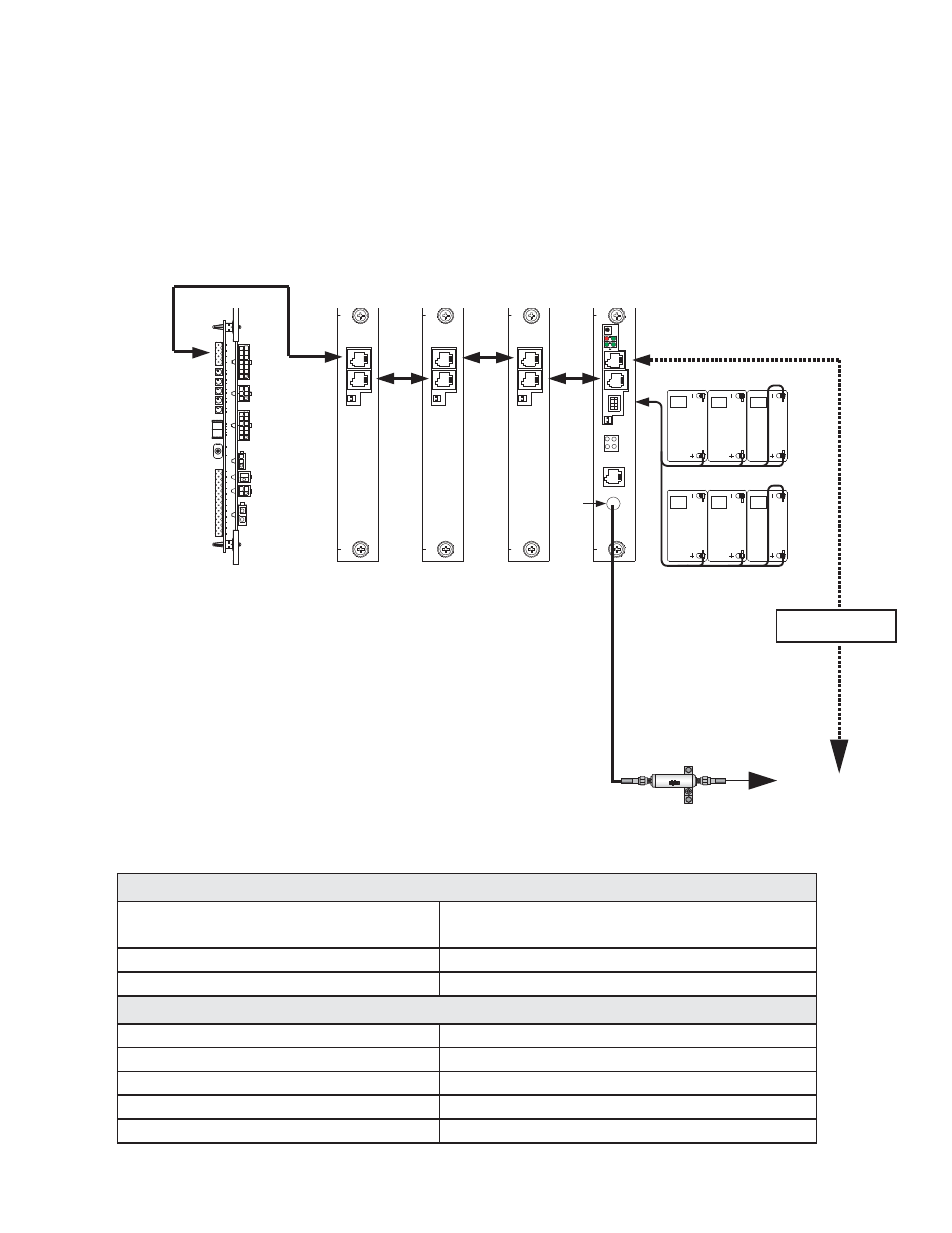
1.0 Introduction,
continued
1.1 System
Layout
The diagram below shows a typical power supply system using either an embedded or
external digital transponder.The EDSM can monitor up to six (6) power supplies, two battery
strings via the AUX connector, and one (1) generator. The EDSM collects data from these
devices and relays it to the head end using a digital transponder.
System Part Numbers:
EDSM with DT Connector
745-678-20
EDSM Sheet Metal/Faceplate
745-427-21
XMS2 Serial Interface
704-742-20
AlphaBus Communications Cable
874-460-20
Available Battery Sense Wire Kits:
874-842-21
WR KT,BAT SNSE,COMM MDL,36V 1STR,6'
874-842-27
WR KT,BAT SNSE,COMM MDL,36V 1STR,9'
874-842-28
WR KT,BAT SNSE,COMM MDL,36V 2STR,9'
874-841-21
WR KT,BAT SNSE,COMM MDL,48V 1 STR,6'
874-841-20
WR KT,BAT SNSE,COMM MDL,48V 2 STR,6'