5 dip switch – Alpha Technologies EDSM User Manual
Page 14
704-721-C0-004, Rev. D
14
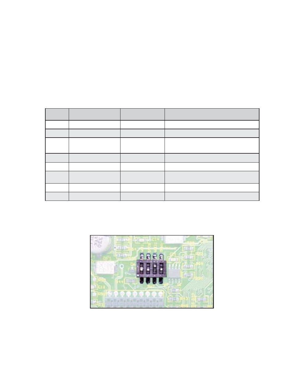
Fig. 2-5, DIP Switch Location
Table 2-2, DIP Switch Settings
2.0 Connectors and Indicators, continued
2.5 DIP
Switch
The on board DIP Switch (SW2) is used to confi gure the tamper polarity, provide RS-485
biasing per the ANSI/SCTE25-3 Specifi cation, and to enable programming. The factory
default switch settings are in the OFF position, with the exception of #3 in the ON position.
The tamper polarity switch allows for either a N/O or N/C switch to be used for enclosure door
monitoring. The ANSI/SCTE25-3 specifi cation requires the RS-485 signals to be optionally
biased to the Vcc and ground of the equipment. The programming mode switch setting is
used during programing of the micro controller. SW4 MUST be in the OFF position for normal
operation of the EDSM. For most transponders, SW3 must be in the ON position.
Switch # Position Description
Function
Description
1
OFF [default]
Tamper Polarity
Normally Closed
1
ON
Tamper Polarity
Normally Open
2
OFF [default]
HMS Pullup/down
RS-485(+) Pulled Up
RS-485(-) Pulled Down
2
ON
HMS Pullup/down
No Bias
3
OFF
HMS Line Balance
No Balance
3
ON [default]
HMS Line Balance
RS-485 lines tied through
120 Ohm resistor
4
OFF [default]
Program
User Mode
4
ON
Program
Programming Mode