2 stat switch, 0 connectors and indicators, continued – Alpha Technologies EDSM User Manual
Page 11
704-721-C0-004, Rev. D
11
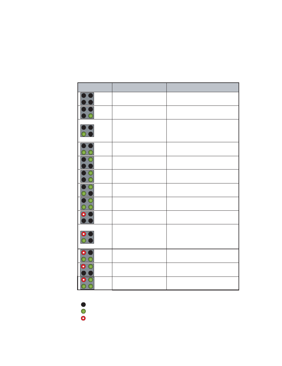
Table 2-1, Alarm Codes
2.0
Connectors and Indicators, continued
2.2 STAT Switch
The momentary push-button labeled "STAT" on the front panel has two functions. When
held down MORE than 3 seconds, the microcontroller will reset. If held down LESS than
2 seconds, the LED matrix will display any faults being reported to the microcontroller.
Repeated presses of the STAT button will display subsequent alarms. The table below lists
all of the valid error codes.
Legend:
Unlit LED
Green Lit LED
Red Lit LED
ALM/RDY
DT/COM
ALM/RDY
DT/COM
Display
Alarm
Definition
ALM/RDY
DT/COM
ALM/RDY
DT/COM
ALM/RDY
DT/COM
ALM/RDY
DT/COM
ALM/RDY
DT/COM
ALM/RDY
DT/COM
ALM/RDY
DT/COM
ALM/RDY
DT/COM
ALM/RDY
DT/COM
ALM/RDY
DT/COM
ALM/RDY
DT/COM
This code is not used.
Reserved
Battery System Fault
EOD Imminent
Tamper
Reserved
System Addressing Fault
System Test Failure
XM2 Alarm
ECM Alarm
Confi guration Error
Self Test Fail
Daughter Board Status
No Alarm
Line loss, batteries cannot support
backup power much longer.
Battery string is too low or too high.
Battery delta is too great.
No batteries detected.
Cabinet intrusion.
Indicated program switch is on.
System device has an invalid address.
Battery or inverter failure.
An XM2 is reporting alarm status.
The generator is reporting alarm status.
Lost communication with XM2.
No temp probes found.
XM2 has confi guration error.
Some XM2s see line, others do not.
EDSM failed self-test on initial power up.
Daughter board Battery Sense is missing
or failed.
Normal condition, no alarms reported.