Ecm xm2, Master – Alpha Technologies EDSM User Manual
Page 18
704-721-C0-004, Rev. D
18
ECM
XM2
with SI Connector
XM2
with SI Connector
XM2
with SI Connector
Head
End
3.0
Module Installation, continued
3.1
XMS2 Communication Module Removal Procedure, continued
12. Slide the inverter module sheet metal into the card guides of the power supply and
reconnect the ribbon cable to the connector and latch the locking pins.
13. Using ONLY the handle on the front of the inverter module, fi rmly seat the inverter
module into the power supply and tighten the thumb screws.
14. Verify that the BATTERY BREAKER is in the OFF position.
15. Reconnect the battery pack to the inverter module, and set the BATTERY BREAKER to
the ON position.
16. Reconnect all other cables and sensors.
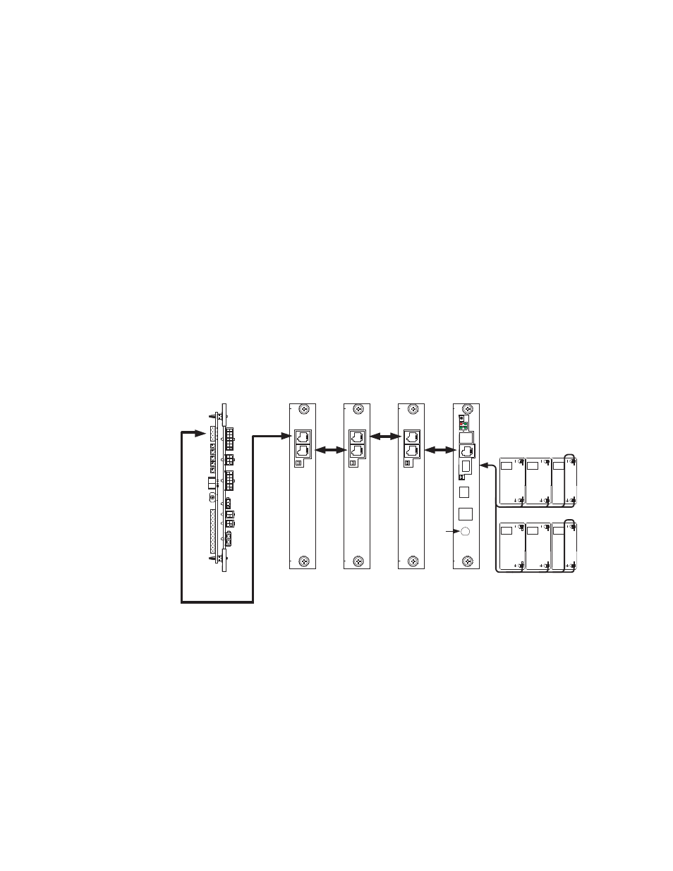
17. Connect devices to the EDSM as shown below.
18. Verify and program if necessary all XMS2 power supplies to a unique address (1 through
7) via the XM2 (refer to XM2 Technical Manual Smart Display Set Up Menu). Refer to the
AlphaGuard manual for CMM hookup.
Fig. 3-3, Device Interconnection
C
O
M
RF
C
O
M
S
Y
S
C
O
M
S
Y
S
C
O
M
S
Y
S
A
U
X
36V
24V
12V
3A
2A
1A
36V
24V
12V
3A
2A
1A
D
T
"Master "
XM2 with EDSM/Embedded Xpdr
- AlphaCell GelCell Series (32 pages)
- FXM 650, 1100, 2000 UPS (96 pages)
- Cordex 48-1.2kW (68 pages)
- Radium MiniBay (57 pages)
- Fiber Backhaul Enclosure (FBE) (19 pages)
- FBE2322 Enclosure System (38 pages)
- FlexNet PMR, GMR Series (49 pages)
- Te25xh (38 pages)
- FlexNet MPS48-12M - Technical Manual (33 pages)
- FlexNet MPS48-12M - Quick Start Guide (2 pages)
- FlexNet ELPM 300-48D (25 pages)
- FlexNet FMPS (40 pages)
- FlexPoint AX Series (34 pages)
- FlexPoint FPR1207-F - Technical Manual (18 pages)
- FlexPoint FPR1207-F - Quick Start Guide (2 pages)
- AlphaGen PN-6x-T 7.5kW 48VDC - Installation and Operation Manual (79 pages)
- AlphaGen CE-3x2 5K-T 48Vdc (95 pages)
- AlphaGen PN-6x-T 7.5kW 48Vdc (95 pages)
- AlphaGen 3.5_5.0kW Kohler COM5 (80 pages)
- Security Bar Field For UPE-3, UPE-6, UPE-M3, UPE-M6, PN Series and CE Series (2 pages)
- AMPS80 HP (116 pages)
- 255A Bypass Switch (24 pages)
- AMP24 HP (108 pages)
- FXM350_Micro350 UPS (112 pages)
- CFR 600, CFR 600XT, CFR 1000 (70 pages)
- BPS Series Bypass Switch (36 pages)
- CFR Intelligent Interface Device (54 pages)
- CFR Redundant Control Unit (23 pages)
- CFR 5000, CFR 5000RM (88 pages)
- CFR 3000, CFR 3000RM (86 pages)
- CFR 1500, CFR 1500RM (83 pages)
- CFR 1500, CFR 2000, CFR 2500, CFR 3000 (76 pages)
- Continuity: 1000_2000_3000 (48 pages)
- Continuity Battery Pack (20 pages)
- Continuity: 6K_10K (52 pages)
- Micro, Micro XL, Micro XL3 UPS (99 pages)
- Micro Secure UPS (80 pages)
- Te17 (32 pages)
- Te45 (68 pages)
- Te41, 48V (76 pages)
- Te41, 24V (72 pages)
- Te43 (60 pages)
- AlphaGuard AG-CMT Installation (2 pages)
- AlphaGuard AG-CMT-3SC_4SC-P (2 pages)
- Digital Midtron DM-3200 AT (2 pages)