5 wiring – Alpha Technologies CXPS-HD 48-1.2-225 User Manual
Page 24
0530082-J0 Rev B
Page 16 of 31
5 Wiring
This chapter provides cabling details and notes on cable sizing for DC applications.
WARNING Ensure that the power is removed by turning off rectifiers and removing battery line
fuses or connections before attempting work on the wiring connections. Use a voltmeter to verify
the absence of voltages. Clearly mark the correct polarity of the battery leads before working on
DC connections.
Refer to the Installation chapter for safety precautions and tools required.
5.1 Grounding
Connect the isolated power system battery return bus (BRB) to the building master ground bus (MGB) or floor
ground bus (FGB) in larger buildings. This acts as a system reference and a low impedance ground path for
surges, transients, noise, etc. The MGB or FGB should have a direct low impedance path to the building
grounding system. Size the cable between the power system and the MGB or FGB so that there is sufficient
ampacity to clear the largest fuse or breaker on the power system, excluding the battery protection fuse or circuit
breaker. This is the minimum requirement. Other factors including length of cable and special grounding
requirements of the load must be factored in. The insulated cable should be equipped with two-hole crimp type
lugs and should not have any tight bends or kinks.
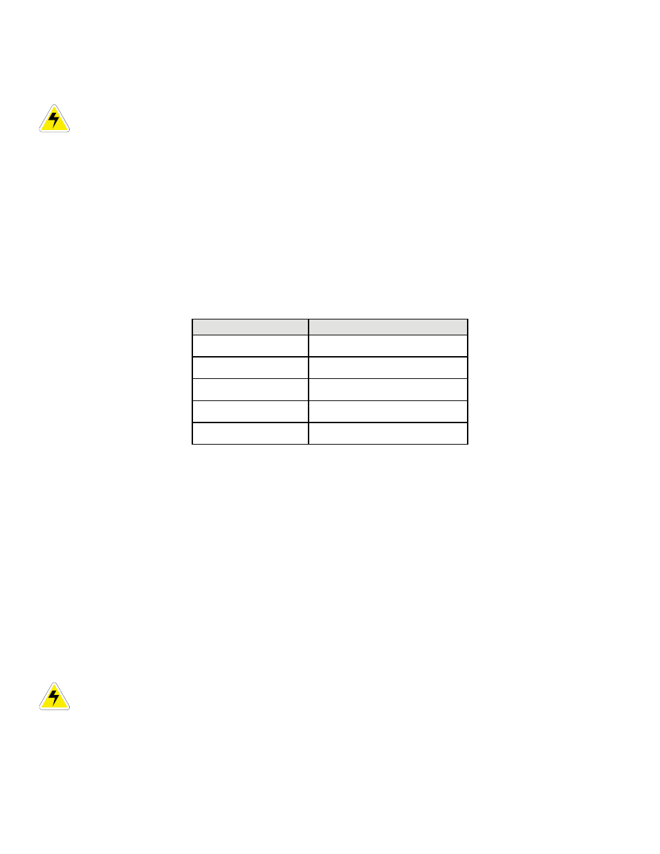
Power system ampacity Ground reference conductor size
< 30 A
#10 AWG
30 – 100 A
#6- #2 AWG
100 – 400 A
0000 AWG
400 – 800 A
350 MCM
> 800 A
750 MCM
Table B–Typical ground reference conductor selection
The power system frame must also be connected to the MGB or FGB for safety reasons and to meet standard
Telco grounding requirements. Each bay must have its own frame or site ground connection. Refer to the
customer connections drawing at the rear of this manual.
5.1.1 Frame
ground
The distribution panel is grounded to the relay rack via screws/bonding washers, and then uses 35 mm
2
(#2 AWG) insulated cable to connect to the main grounding bus.
5.2
AC feeder protection/sizing
To maximize system reliability, each power module should be fed from a dedicated protection feeder breaker
located at the AC distribution panel. The feeder breaker can also be used as a disconnect device for the
connected module. Refer to the specifications in this manual for Alpha recommendations.
5.3
AC input connections
CAUTION: AC input wires must be routed in flexible or rigid conduit as far away as possible from
DC power wires to minimize EMI disturbances.
Ensure that all modules are removed from the shelf. Refer to customer connections drawing. The shelf
incorporates IEC plug connections, which require line cords with C19R type receptacles. See ordering information
for available cords.