Alpha Technologies CXPS-HD 48-1.2-225 User Manual
Page 14
0530082-J0 Rev B
Page 6 of 31
2.3.7.3 Temperature
inputs
Two temperature input channels, T1 and T2, provide monitoring of battery temperature and temperature
compensation (temp comp) or room/ambient temperature. Voltage is supplied to these terminals to power the
temperature sensors.
2.3.8 Digital
input
channels
The controller can accommodate up to two (2) digital input channels that can monitor digital alarm/control signals
from rectifiers, converters, and other types of equipment.
2.3.9
Alarm and control output relays
The controller contains four (4) Form C digital alarm output relays, which are used to extend alarms and control to
external apparatus. Each internally generated alarm or control signal may be mapped to any one of these relays,
or several signals may be mapped to just one relay or none at all.
2.3.10 Network
connection
and remote communications
The Cordex system can be set up, monitored, and tested via an Ethernet 10/100 Base-T serial data connection.
The communication protocol supports a web interface. A CAN bus is used to transmit all alarm and control
functions between the controller and rectifiers.
2.4 Rectifiers
The rectifier modules employ an advanced resonant power conversion technology with high power conversion
efficiency. All internal semiconductor devices operate under “soft-switching” conditions and exhibit very low power
loss. The reduced power loss leads to lower thermal stresses on the semiconductors and thus improves reliability.
Sustaining low component temperatures is the primary factor with meeting three worst-case field scenarios: 65°C
ambient temperatures, full output power, and low AC input (176 Vac). While meeting these specifications, Cordex
rectifiers are roughly twice as reliability at 55°C ambient temperature and up to four times more at 45°C.
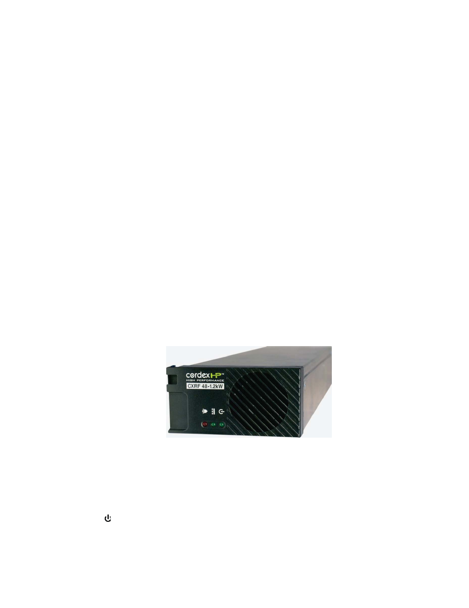
2.5
Rectifier front panel
Figure 3–Rectifier front panel
2.5.1 LEDs
Three front panel LEDs are uses to show the rectifier status and to help locate a specific rectifier module that is
under the control of the controller.
2.5.1.1 AC
The top green LED illuminates continuously when the AC input power is within the acceptable range and the
rectifier is delivering power to the load. It flashes when the AC input power is outside the acceptable range. This
happens when the AC Mains Low or AC Mains High alarms are activated. This LED is off when there is no AC
input power.