Alpha Technologies CXPS-HD 48-1.2-225 User Manual
Page 13
0530082-J0 Rev B
Page 5 of 31
2.3.3 LED
lights
Three LED lights are located on the front panel, one green, one yellow, and one red. The lights are used to
display the alarm status of the power system, controller progress and status during startup, and file transfers.
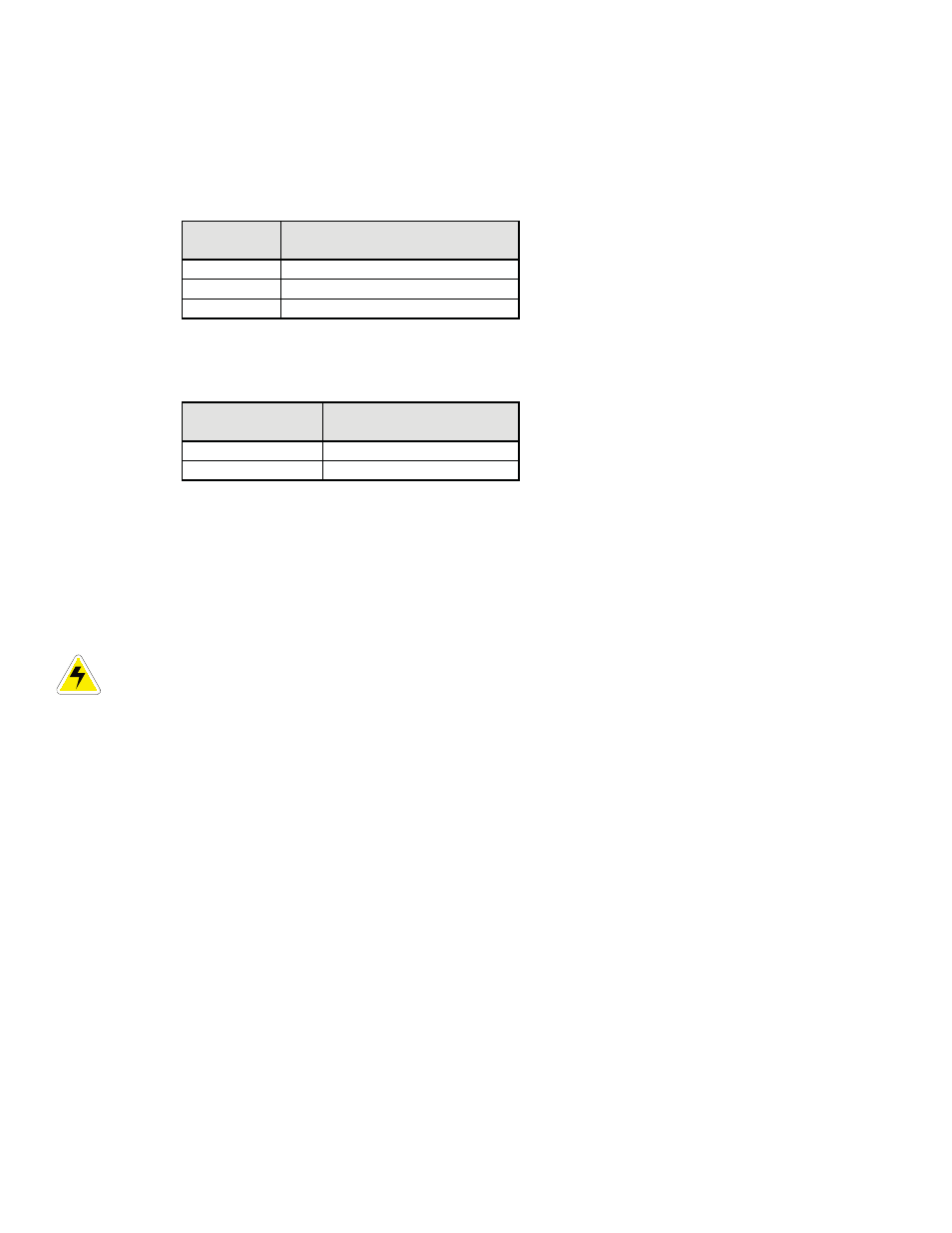
2.3.3.1 Alarm
conditions
Only one LED light is illuminated at a time during alarm conditions. Each LED light corresponds to a specific
alarm.
Illuminated
LED light
Alarm
Green
OK, no alarms
Yellow
Minor alarm, no major alarms
Red Major
alarm
2.3.3.2 Progress
and
status
indication
The LED lights are also used in the following situations:
Illuminated
LED light
Situation
All three
Base unit validation
Red File
transfer
2.3.4 Reset
button
A reset button is located on the front panel for restarting the controller’s microprocessor. Select the reset menu
item before pressing the reset button. Refer to the software manual.
2.3.5 Modem
port
A modem port is located on the front panel. It is designed to be used in conjunction with an Alpha DB-9 connector
and an Alpha Cordex DC Modem #018-585-20.
CAUTION: Connect the modem port with an Alpha-supplied modem and cable only. Otherwise,
equipment damage may result.
2.3.6 Ethernet
port
An Ethernet port is located on the front panel. This port is designed to connect the controller to a user supplied
TCP/IP network. Use a standard RJ-45 jack with a standard network cable.
The Ethernet port can be used for local access, for example to a laptop computer. Use a standard network
crossover cable for the connection.
2.3.7
Analog input channels
The controller is supplied with analog input channels for voltage, current, and temperature.
2.3.7.1 Voltage
inputs
Two voltage input channels, V1 and V2, are used to monitor the discharge and charge voltage. The controller
software is pre-configured to monitor V1 for load voltage and V2 for battery voltage. V2, which is wired internally,
is used as a system reference for the rectifier float voltage, low voltage disconnect (LVD), system high voltage
alarm, and system low voltage alarm.
2.3.7.2 Current
inputs
The controller software is pre-configured to monitor I1 for load current. It is wired internally to the system current
shunt.