Alpha Technologies CXDS-M 600_600-19 User Manual
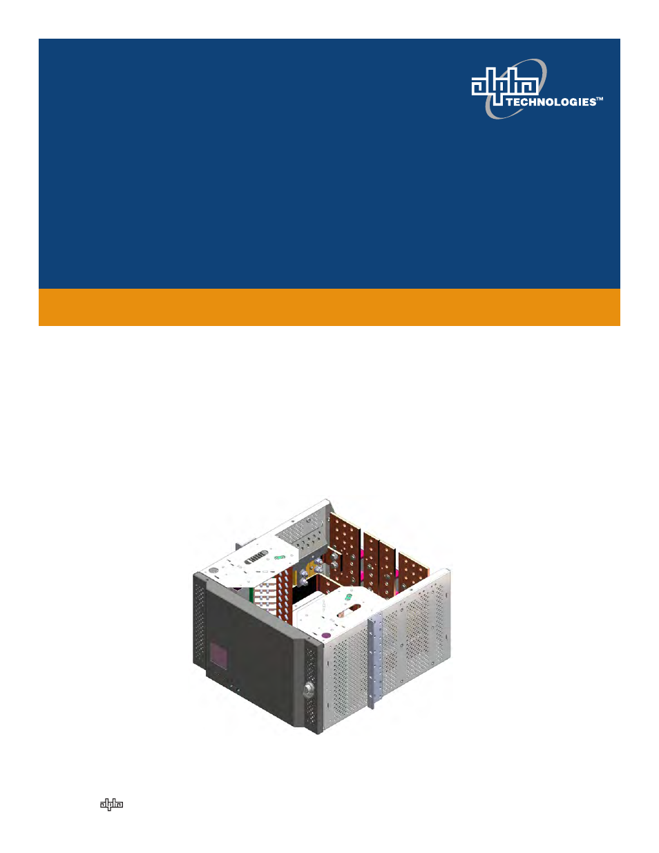
Cordex modular distribution system, Your power solutions partner, Installation & operation manual
This manual is related to the following products:
Table of contents
Document Outline
- 9400002-J0_body_Jun27.pdf
- 1. Safety
- 1.1 Safety Symbols
- 1.2 Mechanical Safety
- 1.3 Electrical Safety
- 1.4 Battery Safety
- 2. Introduction
- 2.1 Scope of the Manual
- 2.2 Distribution and Termination
- 2.3 Cordex System Controller
- 3. Pre-Installation Preparation
- 3.1 Site Selection
- 3.2 Tools and Test Equipment
- 3.3 Unpacking the Equipment
- 4. Installation
- 4.1 Rack Mounting
- 5. Installation - DC and Grounding Cables
- 5.1 Installation Notes
- 5.2 Connecting the Frame and Reference Grounds
- 5.3 DC Input
- 5.4 Connecting DC Load Cables to Breaker/Fuse Circuitry
- 5.5 External Alarm Wiring
- 6. System Startup
- 7. Test and Commissioning Overview
- 7.1 System
- 7.2 Documentation
- 8. Adding an Expansion BDFB
- 9. Maintenance
- 9.1 Controller Lithium Battery Replacement
- 10. Acronyms and Definitions
- 11. Warranty
- 11.1 Battery Warranty
- Figure 1 — Cordex BDFB, dual feed with isolated returns
- Figure 2 — Example of a distribution system with two BDFBs
- Figure 3 — Breaker bank shunt (left shunt shown in a dual feed BDFB)
- Figure 4 — Shunt mux panel mounted on the inside door of the top BDFB
- Figure 5 — Fuse/breaker alarm LEDs and shunt multiplexer reset button
- Figure 6 — CXCP controller mounted in a distribution BDFB
- Figure 7 — Controller communication ports
- Figure 8 — Controller I/O and alarm interface
- Figure 9 — BDFB installation shield
- Figure 10 — BDFB with center mount brackets
- Figure 11 — Battery return reference
- Figure 12 — DC Input bus bars
- Figure 13 — Preparation for 2-pole and 3-pole breakers
- Figure 14 — Load cable connection to BDFB
- Figure 15 — Final load cable arrrangement (4 distribution BDFBs shown)
- Figure 16 — Route of external signal wiring
- Figure 17 — Top Kydex cover with cuts for cable entry
- Figure 18 — Cable tie bar and insulation shield
- Figure 19 — BDFB bottom covers
- Figure 20 — Alignment of filler plates and bus bar connectors
- Figure 22 — I/O and Alarm Interface board
- Figure 21 — BDFB back cover installation
- 1. Safety
- 9400002-J0_body_Jun27.pdf
- 1. Safety
- 2. Introduction
- 3. Pre-Installation Preparation
- 4. Installation
- 5. Installation - DC and Grounding Cables
- 6. System Startup
- 7. Test and Commissioning Overview
- 8. Adding an Expansion BDFB
- 9. Maintenance
- 10. Acronyms and Definitions
- 11. Warranty
- Figure 1 — Cordex BDFB, dual feed with isolated returns
- Figure 2 — Example of a distribution system with two BDFBs
- Figure 3 — Breaker bank shunt (left shunt shown in a dual feed BDFB)
- Figure 4 — Shunt mux panel mounted on the inside door of the top BDFB
- Figure 5 — Fuse/breaker alarm LEDs and shunt multiplexer reset button
- Figure 6 — CXCP controller mounted in a distribution BDFB
- Figure 7 — Controller communication ports
- Figure 8 — Controller I/O and alarm interface
- Figure 9 — BDFB installation shield
- Figure 10 — BDFB with center mount brackets
- Figure 11 — Battery return reference
- Figure 12 — DC Input bus bars
- Figure 13 — Preparation for 2-pole and 3-pole breakers
- Figure 14 — Load cable connection to BDFB
- Figure 15 — Final load cable arrrangement (4 distribution BDFBs shown)
- Figure 16 — Route of external signal wiring
- Figure 17 — Top Kydex cover with cuts for cable entry
- Figure 18 — Cable tie bar and insulation shield
- Figure 19 — BDFB bottom covers
- Figure 20 — Alignment of filler plates and bus bar connectors
- Figure 22 — I/O and Alarm Interface board
- Figure 21 — BDFB back cover installation