3 recommended torque values, 4 cabling layout, 5 alarms – Alpha Technologies CXDS-M 600_600-19 User Manual
Page 22
9400002-J0 Rev A
20
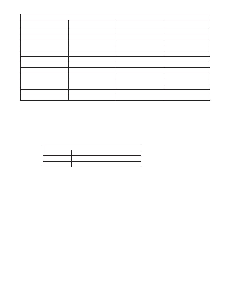
Table C — Cable size equivalents (AWG to Metric)
Cable size (see notes 1
and 2)
Circular mils
Square millimeters
Equivalent metric cable
6 AWG
26250
13.30
16
4 AWG
41740
21.15
25
2 AWG
66370
33.63
35
0 AWG (or 1/0)
105600
53.48
50 or 70
00 AWG (or 2/0)
133100
67.42
70
0000 AWG (or 4/0)
211600
107.2
120
313 MCM (or kcmil)
313600
159
150 or 185
350 MCM (or kcmil)
350000
177.36
185
373 MCM (or kcmil)
373700
189
185 or 240
500 MCM (or kcmil)
500000
253.36
300
535 MCM (or kcmil)
535300
271
300
750 MCM (or kcmil)
750000
380.00
400
777 MCM (or kcmil)
777700
394
400
5.1.3 Recommended Torque Values
Recommended torque values for connection to the power system:
x
Clear hole connections (nut and bolt)
x
PEM studs
x
PEM threaded inserts
x
Thread formed connections (in copper bus bar)
Table D — Recommended torque values
1/4"
8.8 ft-lbs (105 in-lb)
3/8"
32.5 ft-lbs (390 in-lb)
1/2"
73 ft-lbs (880 in-lb)
SAE Grade 5 hardware is required for these torque values.
5.1.4 Cabling Layout
The cabling at the time of installation is very straightforward.
x
The DC input cables connect to the top BDFB at the rear.
x
The load cables from the BDFB fuse/breaker exit the unit through the top. Open the front door of the
BDFB to access fuse/breaker connections.
x
All signaling wires (for example, alarms from the CXC Controller) interfacing with the outside world
exit the BDFB through the top or bottom.
5.1.5 Alarms
All applicable alarms should be connected to the local alarm-sending unit from the power system. The CXC sys-
tem controller provides form “C” relay contacts for interconnection.