Figure 8 — controller i/o and alarm interface – Alpha Technologies CXDS-M 600_600-19 User Manual
Page 15
13
9400002-J0 Rev A
2.3.4 Analog Inputs
Temperature inputs
Two temperature input channels, T1 and T2, provide monitoring of battery or room/ambient temperature. Voltage
is supplied to these terminals to power the temperature sensors.
Voltage inputs
Two voltage input channels, V1 and V2, are used to monitor the system voltage. The controller software is pre-
configured to monitor V1 for load voltage A and V2 for load voltage B.
Current inputs
The controller software is pre-configured to monitor I1 for load current A and I2 for load current B. It is wired inter-
nally to the system current shunt.
2.3.5 Digital Input Channels
The CXCP can accommodate up to eight digital input channels. Each channel responds to a zero or system volt-
age potential at the input to activate or deactivate the appropriate condition.
Some of these channels are pre-assigned to monitor specific signals. See the software manual for more informa-
tion. Refer also to the electrical schematic that ships with your system.
2.3.6 Alarm and Control Output Relays
Each CXCP contains eight standard and eight optional Form C alarm output relays to extend alarms and control
to external apparatus. Each internally generated alarm or control signal can be mapped to any one of the 16
relays, or, several signals may be mapped to just one relay or none at all.
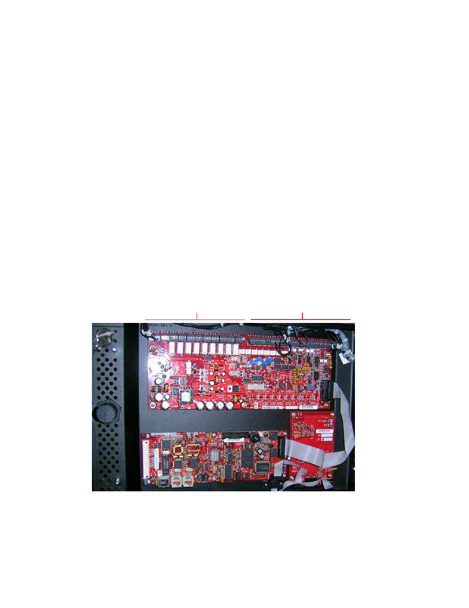
Relays
Digital Inputs
Figure 8 — Controller I/O and alarm interface