Figure 22 — i/o and alarm interface board, Figure 21 — bdfb back cover installation – Alpha Technologies CXDS-M 600_600-19 User Manual
Page 34
9400002-J0 Rev A
32
STEP 5
• Re-install the cable tie bar and insulation shield in
the add-on BDFB (see Figure 18).
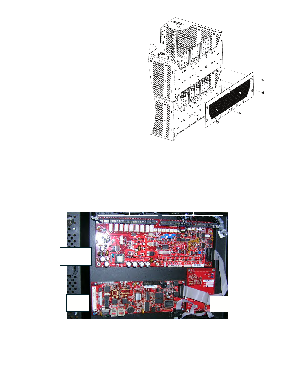
• Install the back cover (Figure 21) on the lower
BDFB (cover ships loose with the BDFB).
Figure 21 — BDFB back cover installation
STEP 6
• Open the front door of the expansion BDFB and locate the inter-BDFB signal cable.
• Open the front door of the BDFB with the controller and remove the inner cover.
• Connect the inter-BDFB cable to the terminal block of the I/O and Alarm Interface board (Figure 22).
• Replace the inner cover.
Signal Wiring
Relays
Digital Inputs
I/O and Alarm
Interface
board
Cordex
Controller
board
LCD
Display
board
Figure 22 — I/O and Alarm Interface board
This manual is related to the following products: