7 charger control interface connector – Alpha Technologies AlphaGen PN-6x-T 7.5kW 48VDC - Technical Manual User Manual
Page 92
92
042-288-B0-001, Rev. A
Fig. 8-7, 48Vdc Charger Control Interface Connector
Pin
Description
Function
1
Line 1, 120Vac AC Line
Sense
The Line side that powers the ECM and Power
PCB, and provides AC line sense to start the
APU.
2
Line 2, Neutral
The Neutral side of the incoming line power.
8.8 ECM AC Line Sense 120/240V Interface
The interface control (J6) is a 2-pin (1x2 row) Mini Mate-’N’-Lok style connector.
Fig. 8-8, ECM AC Line Sense, 120/240V Interface
Pin Description
Function
1
Control Positive
Connects pin 1 & 2 together, turning the Charger ON, i.e. Closed
(LOW signal)
2
Control Negative
Charger control common return
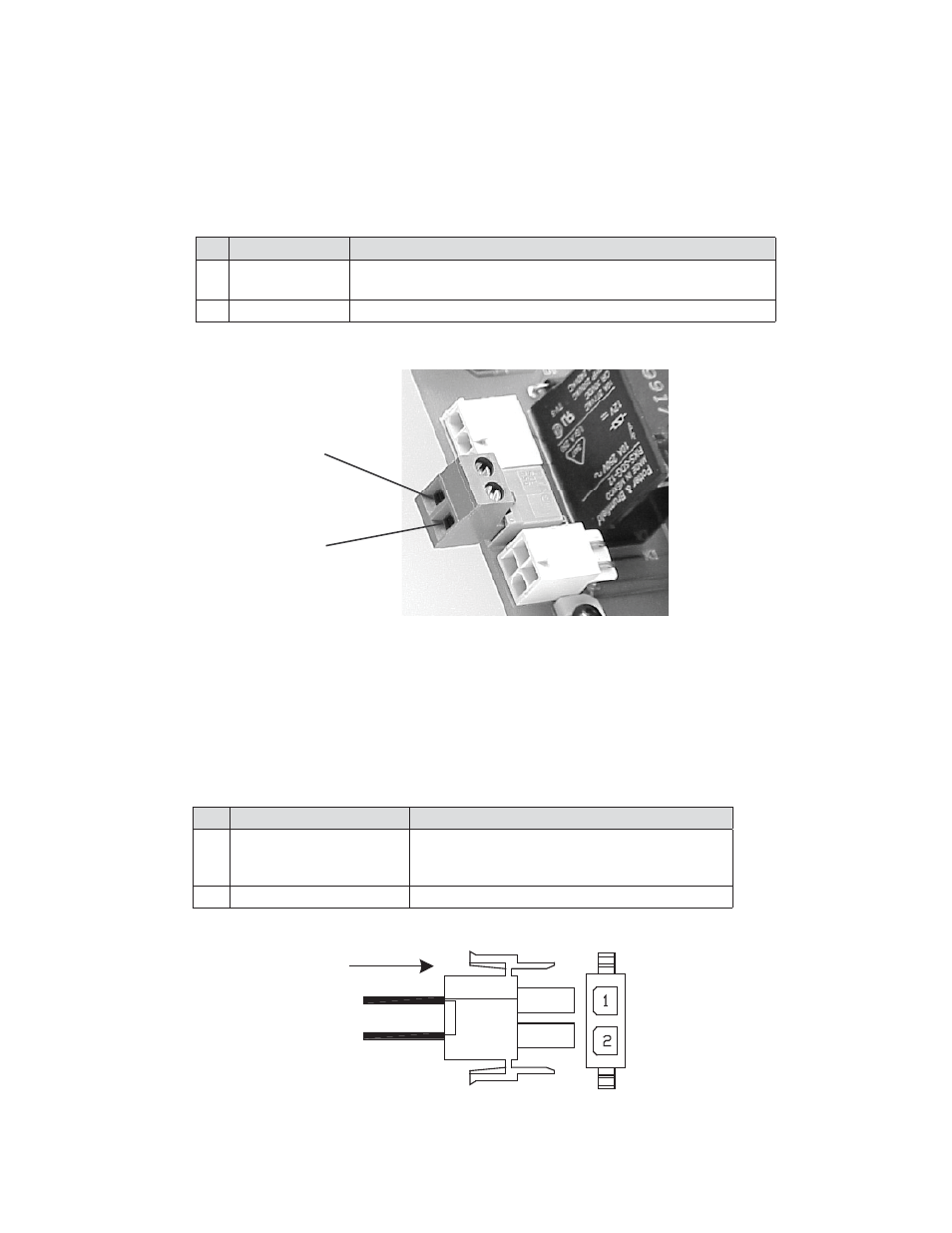
8.0 Interconnection,
continued
8.7 Charger Control Interface Connector
The Battery Charger Control Interface Connector is connected between the charger
module and ECM as shown. The interface control is a terminal block 2-position plug-in
connector.
Pin 1
Pin 2