7 radio cable connection procedure – Alpha Technologies FlexNet MPS48-12M - Technical Manual User Manual
Page 23
23
021-514-B2-001, Rev. A
4.0 Installation,
continued
4.7 Radio Cable Connection Procedure
Recommended Tools and Materials:
Channellock
®
pliers
1. Remove the white seal from the 3-hole strain
relief fi tting and install the base of the fi tting into
the 3/4" knockout, securing the top inside nut.
2. Route the radio cable into the enclosure through the
outer nut and base.
3. Route the Ethernet cable from inside the enclosure, down through the strain relief fi tting.
4. Insert the cables into the seal, leaving about 20" from end routed into the enclosure. The
seal is split in three places to accommodate the cabling. See Fig. 4-5
5. Replace the seal into the base.
6. Secure the outer nut.
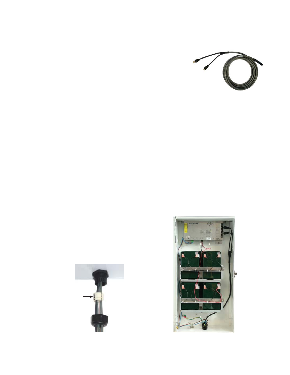
7. Connect the radio cable connectors to the “RADIO, POWER” and “RADIO, SERIAL”
connectors. Connect Ethernet cable to the “ETHERNET BACKHAUL” connector. See Fig.
4-6.
8. Plug any unused holes in the seal (use a short section of wire, or other available
material).
9. Proceed to battery connection procedure. Do Not connect AC power at this time.
Fig. 4-6, 3-hole Strain Relief Fitting
Fig. 4-7, Radio Cable Installed
Base
Seal
Outer Nut
Splits indicated by
dashed lines
Radio Cable