Alpha Technologies FlexNet MPS48-12M - Technical Manual User Manual
Page 19
19
021-514-B2-001, Rev. A
4.0 Installation,
continued
4.4 AC Input (120/230Vac) Connection Procedure
Recommended Tools and Materials:
•
Hammer with punch or screwdriver
•
1" Open-end wrench
• Channellock
®
pliers
•
11/32" (9mm) socket or nut driver
•
#1 Flathead screwdriver
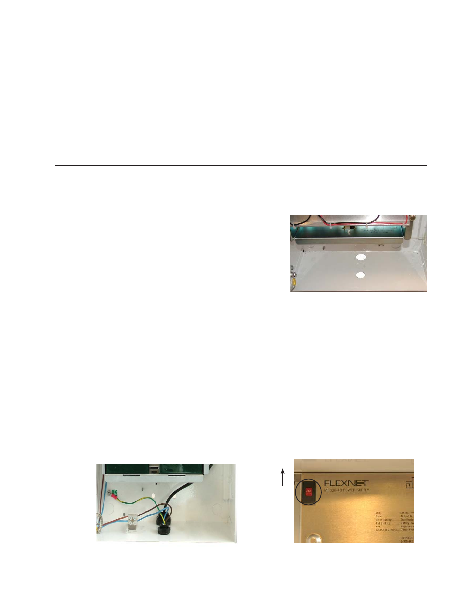
Fig. 4-1, AC Connections
1/2" Knockout
3/4" Knockout
Fig. 4-2, Input Voltage Select Switch
Up for
120V
1. Verify utility power is OFF. Tag and lock utility
power switch.
2. Remove the 1/2" EMT knockout (7/8"
dia.) and the 3/4" EMT knockout (1-1/8"
dia.) located in the center bottom of the
enclosure. For alternate installation, remove
knockouts from the right side, left side, or
back left of the enclosure as needed.
3. Install the provided 1/2" strain relief fi tting, or
user-supplied 1/2" Electrical Metallic Tubing
(EMT) in the front 1/2" knockout. Route the
line cord, or #18AWG wire for line, neutral,
and ground, between the enclosure and utility power connection. When installing the
strain relief fi tting, run the line cord or AC wiring through the bottom retaining nut before
installing the rest of the fi tting. See Fig. 4-1.
4. For 115V applications, connect the line and neutral wires to the AC input block. Torque to
4.5 in-lbs (.5 N m).
For 230V applications, connect L1 and L2 wires to the AC input block. Torque to 4.5 in-lbs
(.5 N m).
5. Using a #10 ring lug, connect a #6AWG ground wire to the #10 ground stud located on
the back wall of the enclosure (see Fig. 4-1). Torque to 36 in-lbs (4.1 N m). See Section
4.6 for recommended grounding procedure.
6. Tighten the strain relief fi tting snug using Channellocks and a 1" wrench.
7. For 120V applications, remove the protective label on the input voltage select switch, and
move the switch to the 115V position. See Fig. 4-2.
ATTENTION:
The user or installer must provide an accessible system disconnect device located near the power supply
enclosure as required by local electrical codes and an overcurrent protection device with a maximum rating of
20A, or as required by local electrical codes.