N-351gf-15_5 – Cla-Val 351GF-15 User Manual
Page 5
5
will be difficult because the sleeve must be in position to per-
mit the ball to recede by gravity out of the path of the reinsert-
ed lockpin with its spring this after getting the ball to enter its
hole from the lockpin gallery.
Reassembly of Model 351GF-15
It is suggested that the following list of new unused O-Rings
should be on hand for reassembly
2 each 00794J
1 only 00779K
1 only 00718H
1 only 200293C Back-up Ring
Materials and tools required
Loctite – Thread locker 222-Service Removable
Grease – To retain Steel balls in sockets and lube O-Rings to
ease installation.
0.250 Hex (Allen) wrench
1/4" Box or open end wrench
3/8" Box or open end or socket wrench
1/4" Box or open end or socket wrench
.045 thick blade screw driver
.094" Hex (Allen) wrench
1/8" or smaller pin or drift punch
Combination slip joint pliers (to hold 28290-01D Pin-link to poppet
stem for installation)
Pedestal (right circle cylinder) or 3"x 3" block both 3" or more
high 14"x14" cut-down box.
One of the 0079J O-Rings can be saved for back-up replacement
on the 28276 Seat Assembly providing the suggestion on pg 4.
about exercising care when removing the 00794J O-Ring has
been followed.
If the 28291-01B Lockpin has been removed it with the 200279-01K
Spring should be reinstalled and retained with the 200275-01D
Screw.
Loctite Thread locker 222 Service Removable or equal on the
200275-01D 8- 32 Screw is recommended.
Reinstallation of the Steel Ball 90290-05K for the lockpin and
the 12 each 90290-06F Steel Balls is facilitated by the use of
a dab of grease in the cavity for each ball to retain them when
installing the 28278-01F Sleeve or length of duct tape.
To install the 28282-01A body with lockpin assembly and Steel
balls into the 28278-01F Sleeve, the sleeve can be inverted on
a smooth bench surface and inside the 14x14 box then the
body carefully inverted and lowered into the sleeve. The
28278-01F Sleeve is carefully lifted and the 28291-01B
Lockpin depressed to provide a indentation recess for the
90290-05K Ball allowing the sleeve to be pulled up capturing
the 12 Steel balls in their sockets, then release the lockpin dri-
ving the 90290-05K Ball to engage the annular detent groove
in the inside diameter of the sleeve. Return the body/sleeve
assembly to the upright position. Install 28289-01F Crank with
the 71988-40G washer into the body.
Note a light coat of grease on the shaft of the crank will aid the
placement of the 00718H O-Ring and back-up ring.
The sequence of reassembly can vary at this point.
A - The crank installation can be completed by placing the
O-Ring and back--up ring followed by the 28287-01K Delrin
bearing, then the handle and its retainer with a drop of Loctite
on the bolt.
B - The 28279-01G Stem Poppet (less the 28280-01E poppet)
can be inserted in the body to a full-up position.
Assembly Aid:
Resting the poppet stem on a cylindrical pedestal of 3 or more
inches high and approximately 3" diameter (an inverted tin
can) will facilitate the next steps of the assembly sequence.
With the assembly resting on the pedestal, rotate the body
while restraining the poppet stem (use the 28283-01J link in
the slot of the poppet stem) to a position such that the slots in
the body are 90º relative to the slots in the poppet.
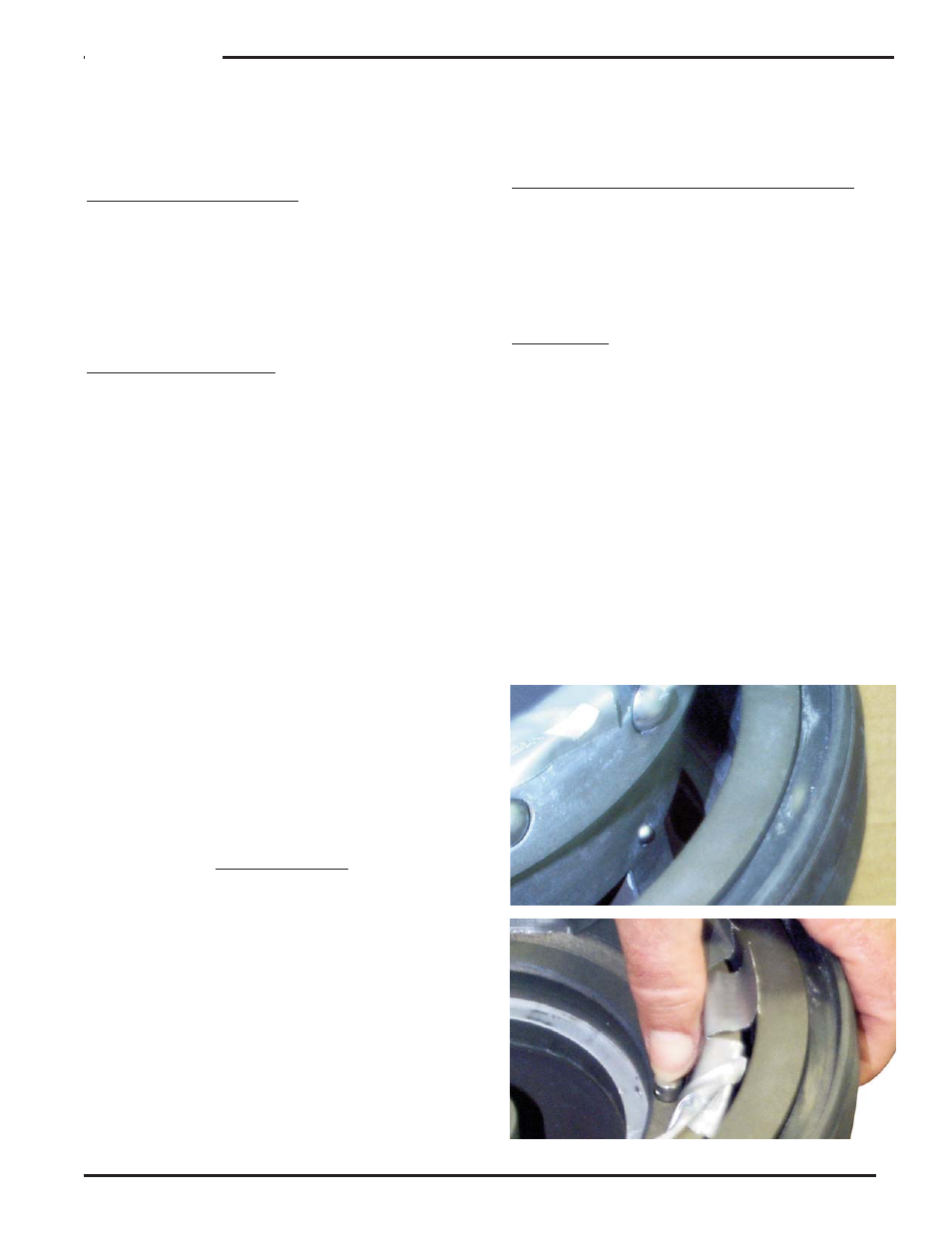
In position as described above, the 5/16" hole in the poppet
stem will be aligned with the slots in the body allowing the
28290-01D Pin to be inserted through the poppet stem and
28283-01J Link. (See Fig 8.) With the link retained in the stem,
the two components can be rotated in the direction of 12
o’clock where the pin will be captured in stem guide area of
the body. With the 200873 Stepped Pin in hand, the link and
crank are aligned by turning and twisting to permit the pin to
be inserted. When the 200873 Pin is in position, the 200874
Spacer is placed on the pin and retained with a Cotter pin.
If option "A" has not been chosen, the O-Ring backup ring
351GF-15