N-351gf-15_4 – Cla-Val 351GF-15 User Manual
Page 4
4
Additional disassembly of the coupler assembly (Fig.1 Pg.1) is
discouraged unless necessary.
If complete disassembly is required, remove poppet, seat
assembly and wave spring as outlined on Pg. 3
Tools required:
•
3/8" open end, box end or socket wrench (for removing
operating handle)
• 1/4" open end, box end or socket wrench
(for 8-32 Hex washer head - find no. 1-24 dwg. 29725)
• 1/8" or smaller pin or drift punch
(to prevent rotation 28291-01B lockpin find no. 1-26 dwg. 29725)
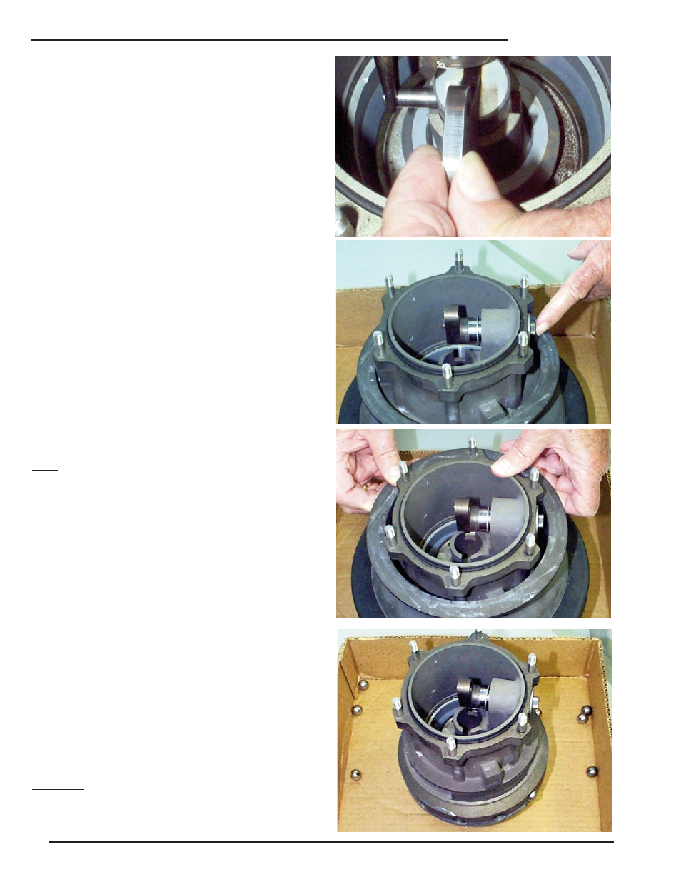
If the 28278-01F Sleeve (See page 2) is to be removed from
the 28282-01A Body (find no. 1-28 dwg. 29725), it is recom-
mended that a cut down 14"x14" corrugated box or tray with
sides two to three inches high be used to prevent loss of 1/4
dia. ball (find no. 1-27 dwg. 29725) and the 12 steel balls,
which are retained by the sleeve.
Having removed the poppet and seat assembly, the poppet
stem is placed in the closed position to provide best access to
the Cotter ring, which is removed with pliers so the stepped pin
can be removed.
At this stage of disassembly it is suggested the relationship of
parts be observed as an aid in reassembly. Position the
assembly with operating handle on the right hand side lifting
the poppet stem by the 28283-01J link high enough to rotate
the link to the 9-o’clock position the 28290-01D Pin (find no. 1-
23 dwg. 29725) can be pushed out. Removing the Pin-Poppet
Stem is aided by a support under the poppet stem and use of
a push rod with 90° short leg, similar to an Allen wrench.
Note:
The poppet stem support method is helpful, almost essential
for reassembly when the poppet stem link attachment pin hole
elevation and orientation must be exact when holding the link
with one hand and reinstalling the 28290-01D Pin.
To remove the crank - required if the 28278-01F sleeve is to
be disassembled.
Remove the 1/4 - 20 Machine Screw holding the 28284-01A
retainer and handle in place on the end of the 28289-01F
Crank
The crank need not be completely removed if the disassembly
purpose is removal of the 28278-01F Sleeve. The crank can
be moved inboard enough to clear the sleeve protecting the
00718H O-Ring and 200293C Backup Ring.
If the 28278-01F Sleeve is to be removed, the item should be
placed in the recommended 14x14 box or tray to contain balls
as they fall from the body.
In the event of complete disassembly, note the position of
washers O-Ring, Backup Ring on the 28289-01F crank as
they are removed.
The 28291-01B Lockpin has not been covered in this disas-
sembly sequence as it can be removed at any time by pre-
venting rotation with a 1/8" dia. or smaller drift punch and
removing the hex washer head 8-32 screw at its other end.
CAUTION:
If the lockpin is removed with the 28278-01F Sleeve in place,
the 200279-01K Spring will eject with the lockpin and the
90290-05K (0.250 dia.) Ball can fall into the pin gallery.
Reassembly of the lockpin with the 28278-01F Sleeve in place
351GF-15