N-351gf-15_2, Open 2 – Cla-Val 351GF-15 User Manual
Page 2
The disconnect can be attached
to the hose while assembled
because it swivels but the 0-Ring
seal causes a lot of drag.
If the disconnect assembly is to
be removed from the elbow cou-
pler assembly for easy attach-
ment to a hose, a 5/32" (4 mm)
Allen wrench is required to
remove the two 10-32 Socket
Head screws retaining the
28296-01B Lock (4") or
200073¬01H Lock (3") allowing
the Spring retaining 4-7 ring to be
expanded out of its groove and
moved back to the groove at the
threaded end of the assembly.
Having moved the Spring
Retaining Ring, the Sleeve Adapter can be moved back which
allows the steel balls to disengage the elbow and be removed.
To reinstall the assembly on its elbow reverse procedure.
With the hose connected to the disconnect assembly and rein-
stalled on the elbow, the coupling assembly can be placed on a
4" API Hydrant conforming to Bulletin API 1584 (2nd Edition 12-
1994).
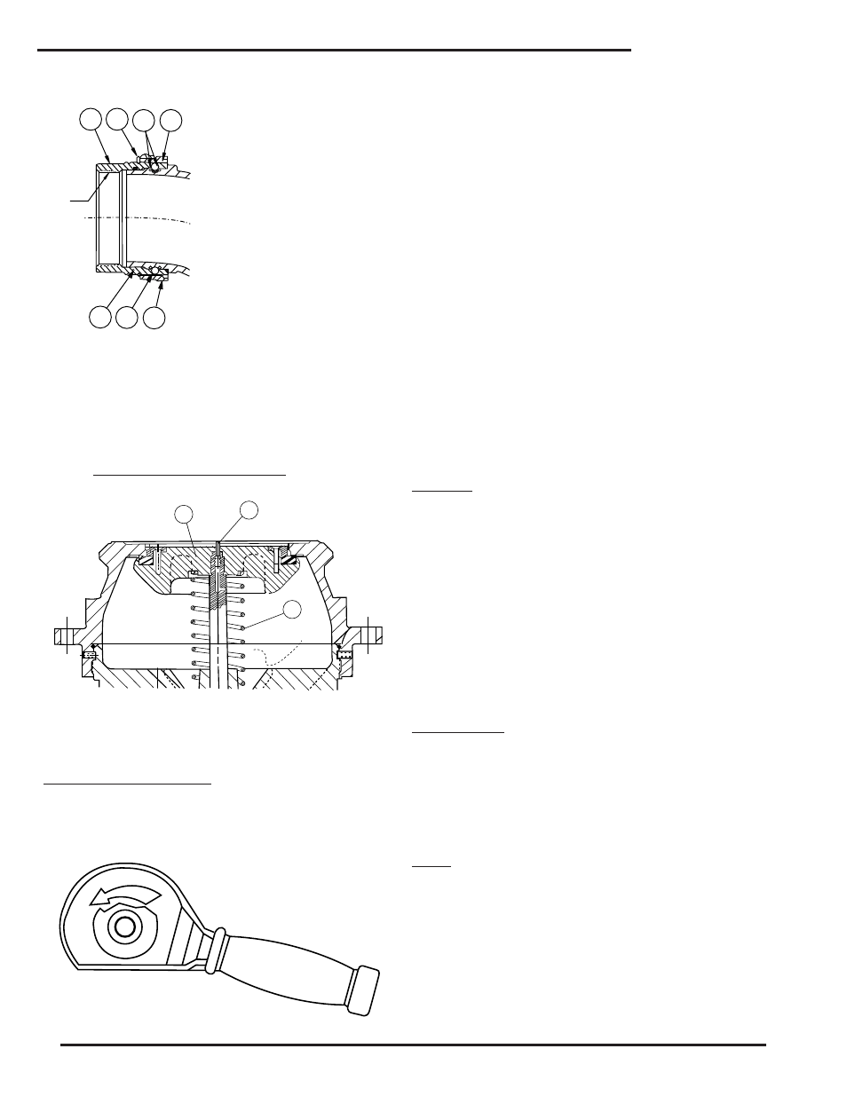
CROSS SECTION OF HYDRANT:
Placement of the hose, disconnect, elbow and coupler on the
hydrant displaces the lockpin (A) (Fig 1, page 1) permitting the
ball (B) to release the sleeve (C) locking the assembly on the
hydrant.
SPECIFICS OF OPERATION.
Rotation of the coupler handle counter clockwise (away from the
hose) approximately 15º will bring the cam portion of the handle
into contact with the sleeve (C) locking it in the down position for
the remainder of any travel of the operating handle in the
counter clockwise direction. Forces involved when the operation
handle is moved are several starting with the first 15º of travel
because the 200277-01B Wave Spring (find no. 1-7 dwg. 29725)
is compressed until the 28289-01F crank (find no. 1-19 dwg.
29725) passes top dead center, then the spring expands driving
the 28276-01C Seat assembly down, keeping it in contact with
the coupler poppet assembly 28281. Next in sequence, the cou-
pler poppet con¬tacts the “Pressure Equalizing Valve” (F) or
poppet on center of the API 1584 hydrant and as travel pro-
gresses, the P.E.V. is depressed equalizing pressure between
hydrant and coupler.
The dimensional relationship between coupler components and
hydrant provides coupler seat assembly driven by wave spring
to make hydrant contact at the time the coupler poppet has
opened to provide a fluid path for the hydrant pressure equaliz-
ing Valve (F) opening, then as the coupler poppet contacts the
hydrant poppet (G), the force required to compress the hydrant
poppet drive spring (H) is evident.
Full stroke of the coupler operating handle positions is approxi-
mately 15º below the horizontal top line of the 28278-01J sleeve
(C) (Handle travel from closed to full open is 210º). At the full
stroke position, both coupler poppet and hydrant pop¬pet are full
open (2” of travel) for max. flow.
Stop flow and removing coupler from hydrant. Move the coupler
operating handle from the open position in clockwise direction.
WARNING
Because of stored energy in the hydrant poppet drive, spring (H)
and fluid pressure under the hydrant poppet, the coupler oper-
ating handle can “FLIP” with considerable force when the
28289-01F CRANK (find no. 1-19 dwg. 29725) moves from its
15º past vertical locked position to the 6 o’clock position (straight
down) and the poppet link and crank are free to be driven by a
force under the hydrant poppet.
Operator should provide a restraining force followed by a push
of 28286-01B handle clockwise to close the coupler poppet and
lock it in its closed position.
With the coupler poppet closed and locked (by 15º past top dead
center of crank), the Sleeve (C) can be lifted releasing the 12
steel balls from the hydrant allowing the coupler to be removed.
Replace the 29762-01A Cover Assembly (find no.3 dwg. 29725).
MAINTENANCE
Replacement of the 28277-01A Guard (find no. 1-4 dwg. 29725).
The coupler with elbow can be removed from the hose by fol-
lowing the procedure outlined on page 1.
Inspection or replacement of the 28276 Seat Assembly, its
00833E O-Ring or the 200277-01B Wave Spring can be accom-
plished as follows:
WARNING
Assure that the hose is not pressurized and is drained before
separating the quick disconnect from the elbow. With the dis-
connect and hose removed, the replacement guard can be
passed over the elbow - and down to the 28278-01F Sleeve. If
the 28286-01B Handle is an interference, depressing the 28291-
01B lockpin and letting the 28278-01F Sleeve drop allows the
handle to rotate to the half travel position for easy pass on the
Nitrile guard. Stretching the guard over the retaining lip of the
sleeve can be difficult and a thick mix of soap in water will help.
Inspection or replacement of the 28276 Seat Assembly, its
00833E O-Ring or the 200277-01B Wave Spring can be accom-
plished as follows:
351GF-15
4 - 6
4 - 7
5
4 - 8
8 N P T
4 - 3
4 - 4
4 - 5
G
F
H
OPEN
2