Cla-val – Cla-Val 250-01/605-01 User Manual
Page 8
Adjustment Ranges (Differential Pressure)
0 to 7 psi 50 to 150 psi
5 to 25 psi 65 to 180 psi
20 to 80 psi
Temperature Range
Water: to 180°F
When Ordering, Please Specify
1. Catalog No. 250-01 or No. 605-01
2. Valve Size
3. Pattern - Globe or Angle
4. Pressure Class
5. Threaded or Flanged
6. Trim Material
7. Adjustment Range
8. Desired Options
9. When Vertically Installed
Pilot System Specifications
Materials
Standard Pilot System Materials
Pilot Control: Bronze ASTM B62
Trim: Stainless Steel Type 303
Rubber: Buna-N
®
Synthetic Rubber
Tubing & Fittings: Copper
and Bronze
Optional Pilot System Materials
Pilot Systems are available with
optional Aluminum, Stainless Steel or
Monel materials at additional cost.
PO Box 1325 Newport Beach CA 92659-0325
Phone: 949-722-4800
Fax: 949-548-5441
CLA-VAL
CLA-VAL CANADA
CLA-VAL EUROPE
4687 Christie Drive
Beamsville, Ontario
Canada LOR 1B4
Phone: 905-563-4963
Fax: 905-563-4040
Chemin dés Mesanges 1
CH-1032 Romanel/
Lausanne, Switzerland
Phone: 41-21-643-15-55
Fax: 41-21-643-15-50
©
COPYRIGHT CLA-VAL 2008 Printed in USA
Specifications subject to change without notice.
www.cla-val.com
E-250-01/605-01 (R-1/08)
Represented By:
605-01 is the reduced internal port size version of the 250-01.
For 100-01 basic valves, suggested, flow calculations were based on flow through Schedule 40 Pipe. Maximum continuous flow is approx. 20 ft/sec (6.1 meters/sec) &
maximum surge is approx. 45 ft/sec (13.7 meters/sec). For 100-20 basic valves, suggested, flow calculations were based on flow through the valve seat.
Approx. 26 ft/sec (7.9 meters/sec) is used for continuous flow & 45 ft/sec (13.7 meters/sec) is used for surge flow. Maximum continuous flow through the valve seat for
the 30" 100-20 is approx. 22 ft/sec (6.7 meters/sec).
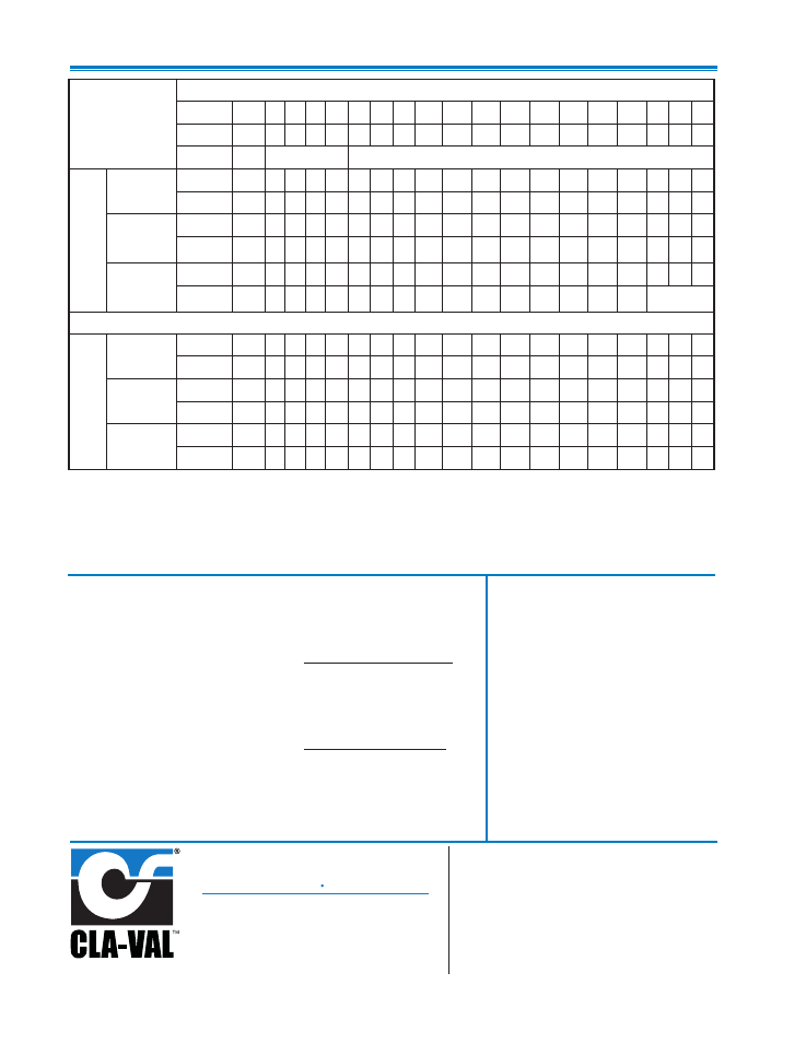
Valve Selection
These Symbols
A
and
B
Indicate Available Sizes
Inches
1
1
⁄
4
1
1
⁄
2
2 2
1
⁄
2
3
4
6
8
10
12
14
16
18
20
24
30
36 42 48
mm
32
40 50 65 80 100 150 200 250 300 350 400 450 500 600 750 900 10001200
End Detail
Threaded Threaded & Flanged
Flanged
Model
250-01
Series
Basic Valve
100-01
Globe
A
A A A
A
A
A
A
A
A
A
A
A
Angle
B
B
B
B
B
B
B
B
B
B
B
Suggested Flow
(gpm)
Max.
Continuous
93 125 210 300 460 800 18003100 4900 7000 8400 11000
25000
Max. Surge
120 280 470 670 100018004000700011000 16000 19000 25000
56500
Suggested Flow
(Liters/Sec)
Max.
Continuous
6
8 13 19 29 50 113 195 309 441 529 693
1575
Max. Surge
13
18 30 42 63 113 252 441 693 1008 1197 1575
3560
Consult Factory for Sizes Not Shown
Model
605-01
Series
Basic Valve
100-20
Globe
A
A
A
A
A
A
A
A
A
A
A
A
Angle
B
B
B
Suggested Flow
(gpm)
Max.
Continuous
260 580 10252300 4100 6400 9230 9230 16500 16500 16500 31300
Max. Surge
440 990 17603970 7050 11000 15900 15900 28200 28200 28200 56500
Suggested Flow
(Liters/Sec)
Max.
Continuous
16 37 65 145 258 403 581 581 1040 1040 1040 1972
Max. Surge
28 62 111 250 444 693 1002 1002 1777 1777 1777 3560
**
Flanged End Detail Only