Dimensions, Materials pressure ratings – Cla-Val 250-01/605-01 User Manual
Page 7
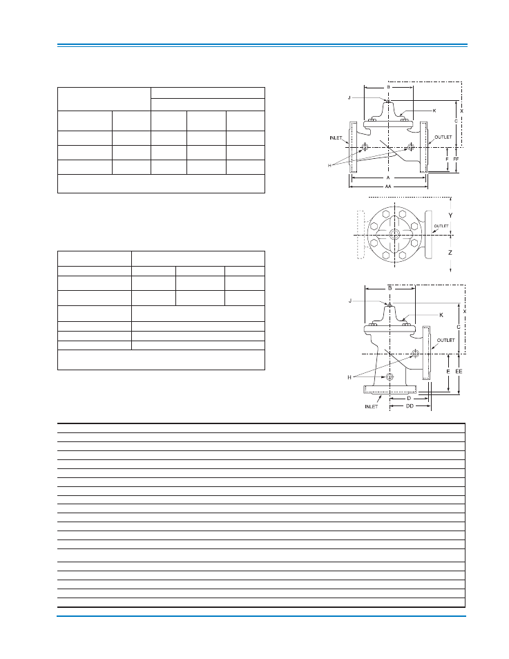
Dimensions
(In inches)
Model 605-01
(Uses Basic Valve Model 100-20)
100-20 (Globe)
Model 605-01 Dimensions
(In Inches)
100-20 (Angle)
Component
Standard Material Combinations
Body & Cover
Ductile Iron
Cast Steel
Bronze
Available Sizes
3" - 48"
3" - 16"
3" - 16"
Disc Retainer &
Diaphragm Washer
Cast Iron
Cast Steel
Bronze
Trim: Disc Guide,
Seat & Cover Bearing
Bronze is Standard
Stainless Steel is Optional
Disc
Buna-N
®
Rubber
Diaphragm
Nylon Reinforced Buna-N
®
Rubber
Stem, Nut & Spring
Stainless Steel
For material options not listed, consult factory.
Cla-Val manufactures valves in more than 50 different alloys.
Materials
Pressure Ratings
(Recommended Maximum Pressure - psi)
Valve Body & Cover
Pressure Class
Flanged
Grade
Material
ANSI
Standards*
150 lb.
300 lb.
ASTM A536
Ductile Iron
B16.42
250
400
ASTM A216-WCB Cast Steel
B16.5
285
400
ASTM B62
Bronze
B16.24
225
400
Note:
*ANSI standards are for flange dimensions only.
Flanged valves are available faced but not drilled.
Valve Size
(Inches)
3
4
6
8
10
12
14
16
18
20
24
30
36*** 42*** 48***
A 150 ANSI
10.25 13.88 17.75 21.38 26.00 30.00 34.25 35.00 42.12 48.00 48.00 63.25 65.00 76.00 94.50
AA 300 ANSI
11.00 14.50 18.62 22.38 27.38 31.50
—
36.62 43.63 49.62 49.75 63.75 67.00 76.00 94.50
B Dia.
6.62
9.12
11.50 15.75 20.00 23.62 27.47 28.00 35.44 35.44 35.44 53.19 56.00 66.00 66.00
C Max.
7.00
8.62
11.62 15.00 17.88 21.00 20.88 25.75 25.00 31.00 31.00 43.94 54.60 61.50 61.50
D 150 ANSI
—
6.94
8.88 10.69
—
—
—
—
—
—
—
—
—
—
—
DD 300 ANSI
—
7.25
9.38
11.19
—
—
—
—
—
—
—
—
—
—
—
E 150 ANSI
—
5.50
6.75
7.25
—
—
—
—
—
—
—
—
—
—
—
EE 300 ANSI
—
5.81
7.25
7.75
—
—
—
—
—
—
—
—
—
—
—
F 150 ANSI
3.75
4.50
5.50
6.75
8.00
9.50
11.00 11.75 15.88 14.56 17.00 19.88 25.50 28.00 31.50
FF 300 ANSI
4.12
5.00
6.25
7.50
8.75 10.25
—
12.75 15.88 16.06 19.00 22.00 27.50 28.00 31.50
H NPT Body Tapping
3
⁄
8
1
⁄
2
3
⁄
4
3
⁄
4
1
1
1
1
1
1
1
1
2
2
2
J NPT Cover Center Plug
1
⁄
2
1
⁄
2
3
⁄
4
3
⁄
4
1
1
1
1
⁄
4
1
1
⁄
4
2
2
2
2
2
2
2
K NPT Cover Tapping
3
⁄
8
1
⁄
2
3
⁄
4
3
⁄
4
1
1
1
1
1
1
1
1
2
2
2
Valve Stem Internal
Thread UNF
10-32
1
⁄
4
-28
1
⁄
4
-28
3
⁄
8
-24
3
⁄
8
-24
3
⁄
8
-24
3
⁄
8
-24
3
⁄
8
-24
1
⁄
2
-20
1
⁄
2
-20
1
⁄
2
-20
3
⁄
4
-16
3
⁄
4
-16
M20
M20
Stem Travel
0.6
0.8
1.1
1.7
2.3
2.8
3.4
3.4
3.4
4.5
4.5
6.5
7.5
8.5
8.5
Approx. Ship Wt. Lbs.
45
85
195
330
625
900
1250 1380 1500 2551 2733 6500 8545 12450 13100
X Pilot System
13.00 15.00 27.00 30.00 33.00 36.00 36.00 41.00 40.00 46.00 55.00 68.00 79.00 85.00 86.00
Y Pilot System
10.00 11.00 18.00 20.00 22.00 24.00 26.00 26.00 30.00 30.00 30.00 39.00 40.00 45.00 47.00
Z Pilot System
10.00 11.00 18.00 20.00 22.00 24.00 26.00 26.00 30.00 30.00 30.00 39.00 42.00 47.00 49.00
Note: The top two flange holes on valve sizes 36 thru 48 are threaded to 1 1/2"-6 UNC.
***Consult Factory