Cla-val, When ordering, please specify – Cla-Val 390-02/3690-02 User Manual
Page 8
CLA-VAL
Copyright Cla-Val 2012 Printed in USA Specifications subject to change without notice.
P.O. Box 1325
• Newport Beach, CA 92659-0325 • Phone: 949-722-4800 • Fax: 949-548-5441 • E-mail: [email protected] • Website cla-val.com
©
When Ordering, Please Specify
1. Catalog No. 390-02 or 3690-02
6. Trim Material
2. Valve Size
7. Adjustment Range
3. Pattern - Globe or Angle
8. Desired Options
4. Pressure Class
9. When Vertically
5. Threaded or Flanged
Installed
E-390-02/3690-02 (R-2/2012)
Adjustment Ranges
2 to 30
psi
15 to 75 psi
20 to 105 psi
30 to 300 psi (factory ranged 40 to 140 psi)
End Connection
3/8" NPT
Temperature Range
Water: to 180°F
Materials
Pilot Control: Bronze ASTM B62
Trim: Stainless Steel Type 303
Rubber:Buna-N
®
Synthetic Rubber
Available with optional Stainless Steel or Monel materials.
Consult factory for details.
Note: Available with remote sensing control (specify CRA-33)
CRD-33 Subassembly Specifications
130VC-3 (CRD-33) Actuator Specifications
Supply Power Input:
12V to 24V DC
No Load draw: 50 mA
Max. Load draw: 250 mA
Remote Command Inputs:
•
4-20mA, analog signal
(isolated and reverse-polarity
protected)
•
Dry contact closure (CW/CCW)
Position Feedback Signal: 4-20 mA
Alarm Output:
Dry-contact closure (High/Low)
Speed of Rotation:
Adjustable On/Off time, max 6 rpm
Diagnostic:
LED Indicator
Loss of Power:
Actuator will remain in last commanded
position.
Loss of Signal Position:
Programmable - 4 mA, Last, or 20 mA
Electrical Connections:
Single, 30 feet of permanently attached
cable with color-coded power supply
and signal wires
Mechanical Specifications:
Environmental
Protection Class:
IP-68 (Temporary submersible)
Ambient Temperature: 15° to 150° F (-10° to 65° C)
Materials
Electronics Enclosure:
Anodized Aluminum
Mechanical Housing:
Bronze
Coupling Assembly:
Stainless Steel
Gear Train:
Stainless Steel, permanently lubricated
We recommend providing adequate space around valve for maintenance work
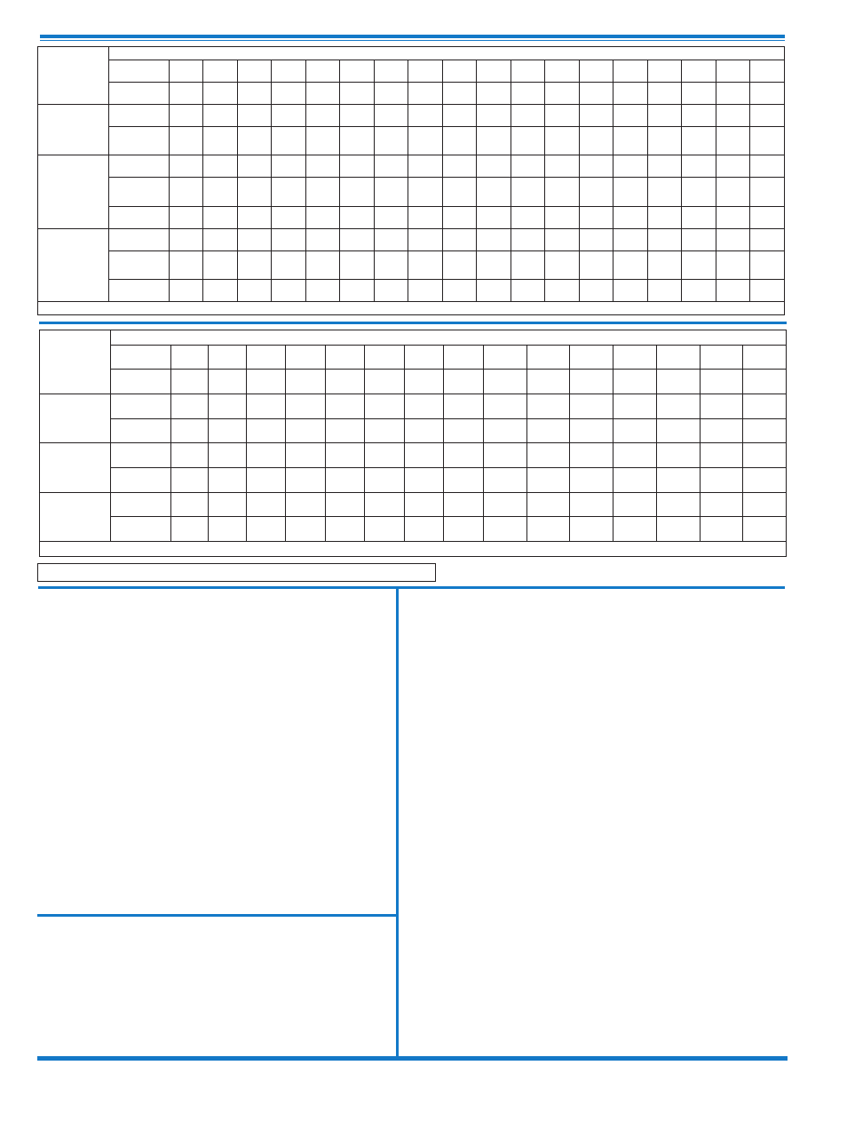
3690-02
Valve
Selection
100-20 Pattern:
Globe (G), Angle (A),
End Connections:
Flanged (F) Indicate Available Sizes
Inches
3
4
6
8
10
12
14
16
18
20
24
30
36
42
48
mm
80
100
150
200
250
300
350
400
450
500
600
750
900
1000
1200
Basic Valve
100-20
Pattern
G
G, A
G, A
G, A
G
G
G
G
G
G
G
G
G
G
G
End Detail
F
F
F
F
F
F
F
F
F
F
F
F
F
F
F
Suggested
Flow
(gpm)
Maximum
260
580
1025
2300
4100
6400
9230
9230
16500
16500
16500
28000
33500
33500
33500
Minimum
1
2
4
10
15
35
50
50
95
95
95
275
450
450
450
Suggested
Flow
(Liters/Sec)
Maximum
16
37
65
145
258
403
581
581
1040
1040
1040
1764
2115
2115
2115
Minimum
.06
.13
.25
.63
.95
2.2
3.2
3.2
6.0
6.0
6.0
17.4
28.4
41.0
41.0
100-20 Series is the reduced internal port size version of the 100-01 Series.
For Lower Flows Consult Factory
390-02
Valve
Selection
100-01 Pattern:
Globe (G), Angle (A),
End Connections:
Threaded (T), Grooved (GR), Flanged (F) Indicate Available Sizes
Inches
1
1
1
⁄
4
1
1
⁄
2
2
2
1
⁄
2
3
4
6
8
10
12
14
16
18
20
24
30
36
mm
25
32
40
50
65
80
100
150
200
250
300
350
400
450
500
600
750
900
Basic Valve
100-01
Pattern
G, A G, A G, A G, A G, A G, A G, A G, A G, A G, A G, A G, A G, A
G
G
G, A
G
G
End Detail
T
T
T, F,
Gr*
T, F,
Gr
T, F,
Gr*
T, F,
Gr
F,
Gr
F,
Gr*
F,
Gr*
F
F
F
F
F
F
F
F
F
Suggested
Flow
(gpm)
Maximum
55
93
125
210
300
460
800
1800 3100 4900 7000 8400 11000 14000 17000 25000 42000 50000
Maximum
Intermittent
68
120
160
260
370
580
990
2250 3900 6150 8720 10540 13700 17500 21700 31300 48000 62500
Minimum
1
1
1
1
2
2
4
10
15
35
50
70
95
120
150
275
450
650
Suggested
Flow
(Liters/Sec)
Maximum
3.5
6
8
13
19
29
50
113
195
309
442
530
694
883
1073 1577 2650 3150
Maximum
Intermittent
4.3
7.6
10
16
23
37
62
142
246
387
549
664
863
1104 1369 1972 3028 3940
Minimum
.03
.03
.03
.06
.09
0.13
0.25
0.63
0.95
2.2
3.2
4.4
6.0
7.6
9.5
17.4
28.4
41.0
100-01 Series is the full internal port Hytrol.
For Lower Flows Consult Factory
*
Globe Grooved Only