Materials, Dimensions, Pressure ratings – Cla-Val 390-02/3690-02 User Manual
Page 7
390-02/3690-02 Purchase Specifications (CRD-33 supplement)
The Electronic Actuated Pressure Reducing Valve shall maintain a constant downstream pressure and shall be capable of remotely
changing this pressure as directed by the hydraulic pressure reducing pilot and integral electronic actuator. The actuator shall provide
the interface between remote telemetry and valve set point control. It shall compare a remote analog signal with an internal position
signal in the actuator and adjust the hydraulic pilot spring mechanism to the new setting. The remote analog signal input shall be iso-
lated and reverse polarity protected. A 4-20 mA actuator feedback signal shall be supplied as standard. A second command control
input shall be available from dry contact switch closure for clockwise and counter clockwise rotation. The actuator shall be IP-68 rated
for submersible service.
If power fails, the pilot shall continue to control the main valve to last set point. If remote set point signal is lost, the actuator shall be
programmable to stay at last position or go to 4 mA or to 20 mA value of set point range. Default is last position. The actuator shall
be ranged at the factory to the specific spring range in the pilot control. If other than the default settings are required, these changes
shall be accomplished by using only the manufacturer’s software and USB cable.
The Electronic Actuated Pressure Reducing Valve shall be Cla-Val Model 390-02/3690-02 as manufactured by Cla-Val, Newport Beach, CA.
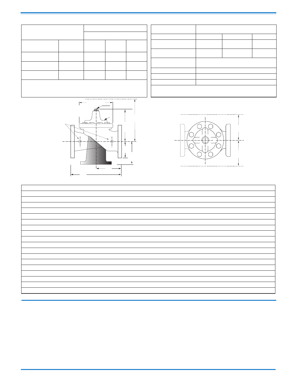
Model 3690-02 Dimensions
(In Inches)
Materials
EE
D
E
Inlet
DD
AA
X
100-20
Flanged
F
A
C
(MAX)
K
J
H
Inlet
Outlet
FF
B
(Diameter)
Dimensions
(In inches)
Component
Standard Material Combinations
Body & Cover
Ductile Iron
Cast Steel
Bronze
Available Sizes
3" - 48"
3" - 16"
3" - 16"
Disc Retainer &
Diaphragm Washer
Cast Iron
Cast Steel
Bronze
Trim: Disc Guide,
Seat & Cover Bearing
Bronze is Standard
Stainless Steel is Optional
Disc
Buna-N
®
Rubber
Diaphragm
Nylon Reinforced Buna-N
®
Rubber
Stem, Nut & Spring
Stainless Steel
For material options not listed, consult factory.
Cla-Val manufactures valves in more than 50 different alloys.
Y
Z
Pressure Ratings
(Recommended Maximum Pressure - psi)
Valve Body & Cover
Pressure Class
Flanged
Grade
Material
ANSI
Standards*
150
Class
300
Class
ASTM A536
Ductile Iron
B16.42
250
400
ASTM A216-WCB
Cast Steel
B16.5
285
400
ASTM B62
Bronze
B16.24
225
400
Note:
* ANSI standards are for flange dimensions only.
Flanged valves are available faced but not drilled.
Valves for higher pressure are available; consult factory for details
Note: The top two flange holes on valve sizes 36 thru 48 are threaded to 1 1/2"-6 UNC.
*Consult Factory
Valve Size
(Inches)
3
4
6
8
10
12
14
16
18
20
24
30
36
42
48
A 150 ANSI
10.25
13.88
17.75
21.38
26.00
30.00
34.25
35.00
42.12
48.00
48.00
63.25
65.00
76.00
94.50
AA 300 ANSI
11.00
14.50
18.62
22.38
27.38
31.50
35.75
36.62
43.63
49.62
49.75
63.75
67.00
76.00
94.50
B Dia.
6.62
9.12
11.50
15.75
20.00
23.62
27.47
28.00
35.44
35.44
35.44
53.19
56.00
66.00
66.00
C Max.
7.00
8.62
11.62
15.00
17.88
21.00
20.88
25.75
25.00
31.00
31.00
43.94
54.60
61.50
61.50
D 150 ANSI
—
6.94
8.88
10.69
CF*
CF*
CF*
CF*
CF*
CF*
CF*
—
—
—
—
DD 300 ANSI
—
7.25
9.38
11.19
CF*
CF*
CF*
CF*
CF*
CF*
CF*
—
—
—
—
E 150 ANSI
—
5.50
6.75
7.25
CF*
CF*
CF*
CF*
CF*
CF*
CF*
—
—
—
—
EE 300 ANSI
—
5.81
7.25
7.75
CF*
CF*
CF*
CF*
CF*
CF*
CF*
—
—
—
—
F 150 ANSI
3.75
4.50
5.50
6.75
8.00
9.50
11.00
11.75
15.88
14.56
17.00
19.88
25.50
28.00
31.50
FF 300 ANSI
4.12
5.00
6.25
7.50
8.75
10.25
11.50
12.75
15.88
16.06
19.00
22.00
27.50
28.00
31.50
H NPT Body Tapping
.375
.50
.75
.75
1
1
1
1
1
1
1
1
2
2
2
J NPT Cover Center Plug
.50
.50
.75
.75
1
1
1.25
1.25
2
2
2
2
2
2
2
K NPT Cover Tapping
.375
.50
.75
.75
1
1
1
1
1
1
1
1
2
2
2
Stem Travel
0.6
0.8
1.1
1.7
2.3
2.8
3.4
3.4
3.4
4.5
4.5
6.5
7.5
8.5
8.5
Approx. Ship Wt. Lbs.
45
85
195
330
625
900
1250
1380
1500
2551
2733
6500
8545
12450 13100
X Pilot System
13
15
27
30
33
36
36
41
40
46
55
68
79
85
86
Y Pilot System
10
11
18
20
22
24
26
26
30
30
30
39
40
45
47
Z Pilot System
10
11
18
20
22
24
26
26
30
30
30
39
42
47
49