Cla-Val 61-02/661-02 Technical Manual User Manual
Page 12
INLETIN
L
E
T
1/8 NPT (THESE
TAPPED HOLES ARE
SHOWN 90" FROM
TRUE POSITION)
INLET
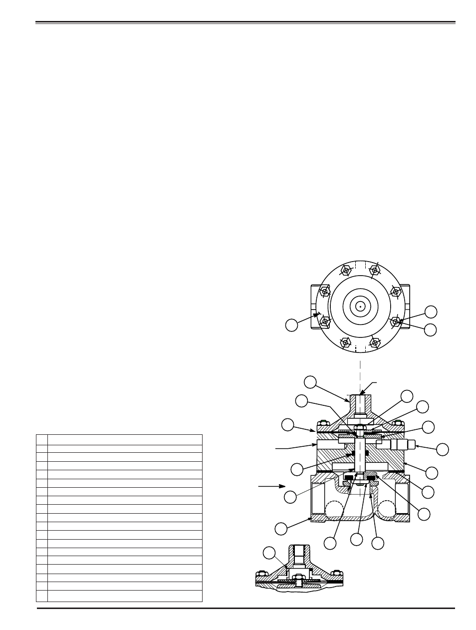
MODELS 100-02KH 100-02KHR, 100-02KHX
16
19
2
17
6
11
8
15
17
9
18
10
12
3
14
7
5
4
13
1
1/8 NPT
1. If the disc has been removed, it is important that correct
pressure be on the disc from the disc guide when the lower
stem nut is tight. Use sufficient spacer washers to obtain
slight pressure (by visual indention) on the disc. Indention
should be slight and no looseness evident. This adjust-
ment applies to 1 " through 16". Refer to seat and disc
detail drawings for location of spacer washers for various
valve sizes.
NOTE: New discs will usually require a different number of
spacer washers to obtain the right amount of "grip'' on the
disc.
2. The stem, with the disc assembly, can now be inserted
through the power unit body. Note sectional view for cor-
rect position of the power unit body and stem assembly
3. Install on the cover end of the stem the lower diaphragm
washer,the diaphragm, the upper diaphragm washer, then
screw on the upper stem nut.
4. Tighten the upper stem nut securely so the diaphragm
and upper and lower diaphragm washer cannot be turned
on the stem. During the tightening of the upper stem nut
the lower stem nut can be held in a vice, or with a second
wrench.
5. Replace the gasket on the body. If an o-ring seal is used
as a gasket, valve size 4" through 16", a light coating of
grease can be applied to the power unit body groove to
hold the o-ring in place while installing on the body. The
power unit body must be replaced so that the index marks
applied in Disassembly Step 1 align. The control tubing will
then be able to be reassembled without difficulty.
6. Replace cover chamber spring on the upper diaphragm
washer. NOTE: Some valves may not have a cover cham-
ber spring.
7. Place the cover on the power unit body aligning the
index marks. Secure the cover with 8 stud nuts. Tighten
the nuts firmly with a cross-over pattern until all nuts are
tight:
8. Reinstall the control system and tubing exactly as it was
before disassembly.
9.The Powertrol Valve can be tested for tight closure as well as
the tightness of the seal across the diaphragm.
a.The downstream or outlet shutoff valve remains closed
b. If the control system has a pilot or control that can position the
valve to a closed position, put the control in a position to close
the Powertrol. Lacking a control, inlet pressure must be tubed to
the Powertrol cover.
c. Open upstream gate or line block valve just enough to allow
flow.
d. Have the power unit body, center section, open to atmosphere
The power unit body will be atmospheric if the control is being
used.
e. Partially disconnect a fitting on the discharge side of the valve.
Do not remove fully unless there is no pressure.
f. After the valve is in the closed position for a few minutes, all
draining of the power unit body should stop. This will indicate a
good seal across the valve seat and the diaphragm.
100-02 POWERTROL
VALVE SIZES 1/2" & 3/4"
1
HEX NUT 10-32 (8)
2 COVER
3 POWER UNIT BODY
4 HEX NUT 1/4-28-NF-2 A.S.F. JAM
5
DIAPHRAGM WASHER (UPPER)
6
DIAPHRAGM
7
DIAPHRAGM WASHER (LOWER)
8
STEM
9
DISC GUIDE
10 DISC RETAINER ASSEMBLY
11 "O" RING
12 BODY TO BODY GASKET
13 STUD 10-32 (8)
14 PIPE PLUG 1/8 NPT
15 BODY
16 SPRING (USED ON 100-02KHR & 100-02 KHX
17 "O" RING
18 SEAT
19 NAMEPLATE
ITEM
NO.
DESCRIPTION