Iii. typical scroll blower – Spencer Single-Stage Scroll Blowers User Manual
Page 7
3
9
12
14
17
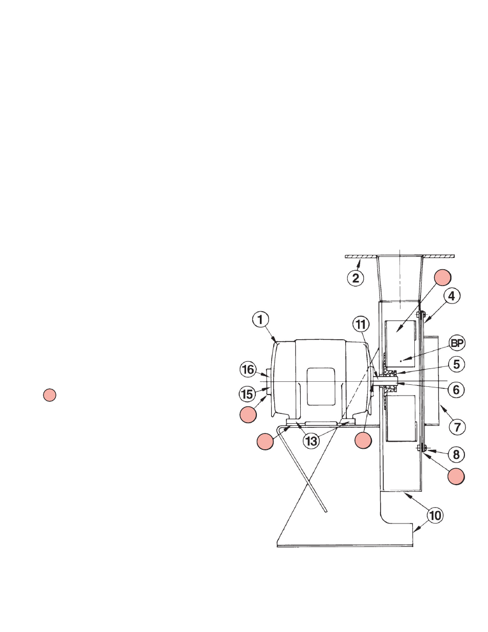
III. Typical Scroll Blower
Note:
1. The impeller is equipped with a split clamped
hub or a tapered bushing clamp (as illustrated).
The latter is tightened on the shaft with three
or six Allen socket screws.
2. Contact Spencer for separate instructions for
arrangement 9 (Belt Drive) single-stage
Scroll Blowers.
Screened items are recommend-
ed spare parts
1 - Front Motor End Bracket
2 - Discharge Flange
3 - Impeller
4 - End Head
5 - Impeller Allen Screws
6 - Motor Shaft
7 - Inlet
8 - End Head Bolts
9 - End Head Gasket
10 - Motor Housing Assembly
(Casing, Motor Base, Floor Support)
11 - Division Head Packing
12 - Rear Motor Bearing
13 - Motor Bolts
14 - Front Motor Bearing
15 - Thrust Bearing Nut
16 - Front Bearing End Cap
17 - Motor Shim
removal of the end head on the other. Removal of
the end head provides immediate access to the
impeller.
To disassemble the scroll blower, proceed as follows:
Remove the bolts (8) securing end head (4) to the
casing assembly. Remove the end head.
Measure or mark position of impeller on the shaft,
loosen the three (or six) Allen socket screws three
full turns, tap the heads of the screws. This will
loosen the impeller from the tapered bushing
allowing removal.
Remove the bolts holding the motor in place.
Remove motor leaving the block and shims in their
original place. The motor can now be overhauled. It
is good maintenance practice and Spencer
recommends replacing the division head packing
(11) when motor removal /reinstallation is
accomplished.
Reassembly
Replace motor in original position on blocking and
shims, making sure that shaft is centered in hole in
division head and taking care not to damage packing
(11). Be sure motor is perpendicular to division head
so that fan is properly aligned within the casing.
Tighten motor hold-down bolts finger tight. Replace
fan and tighten Allen socket screws. Determine (by
hand) that fan turns freely without interference.
Without causing the motor to move, tighten motor
hold-down bolts securely.
Replace end head gasket and end head in proper
position. Insert all bolts. Then tighten uniformly.
Machine is ready to run.
Check that motor leads are properly connected and
motor is rotating in the right direction.
7
The Spencer Turbine Company ◆ 600 Day Hill Road, Windsor, CT 06095 ◆ TEL 800-232-4321 ◆ 860-688-8361 ◆ www.spencerturbine.com
BP - Balancing Point
LP - Lifting Point (Half-moon cutouts in Scroll floor support)