Spencer Single-Stage Scroll Blowers User Manual
Page 4
Coupling alignment lines up the motor shaft and
blower shaft in horizontal and vertical planes. It also
ensures an adequate clearance (gap) between the
two coupling halves. Only qualified personnel should
attempt to align a coupling. If problems arise, contact
Spencer or your Spencer Representative.
Sier Bath Gear-Type Couplings, manufactured to
our rigid specifications, are most commonly supplied
with Spencer equipment.
Sier Bath
Hub to Hub
Coupling Size, In.
Gap, ln.
7/8
1/8
1-1/2
1/8
2
1/8
2-1/2
1/4
3
1/4
3-1/2
1/4
4
1/4
4-1/2
1/4
5
1/4
Remove one snap ring and slide the sleeve off the
hub halves. Using a feeler gage, verify that the gap
between the coupling halves agrees with this table.
Caution: Some motor shafts are spring-loaded
axially. Be careful when using the feeler gage to
avoid compressing the shaft and disturbing the
normal at-rest position.
Machinery Soft Foot
Imperfections or unevenness between the machine
base and any foot of the motor or blower creates a
condition known as soft foot, which may be parallel
or angular. If uncorrected, soft foot leads to increased
stress and high vibration. Although both the motor
and blower feet were preset at the factory, each foot
must be checked for soft foot prior to alignment. Any
vertical or angular soft foot that exceeds .003" is
excessive and must be corrected.
Laser Alignment Technique (Recommended)
Laser systems have significant advantages such as
reduced maintenance costs and energy consumption;
prolonged life for bearings, seals and couplings;
decreased bearing temperatures and lower vibration
levels. Many laser systems also identify and measure
soft foot conditions.
NOTE: Consult an alignment specialist if laser
equipment is not available.
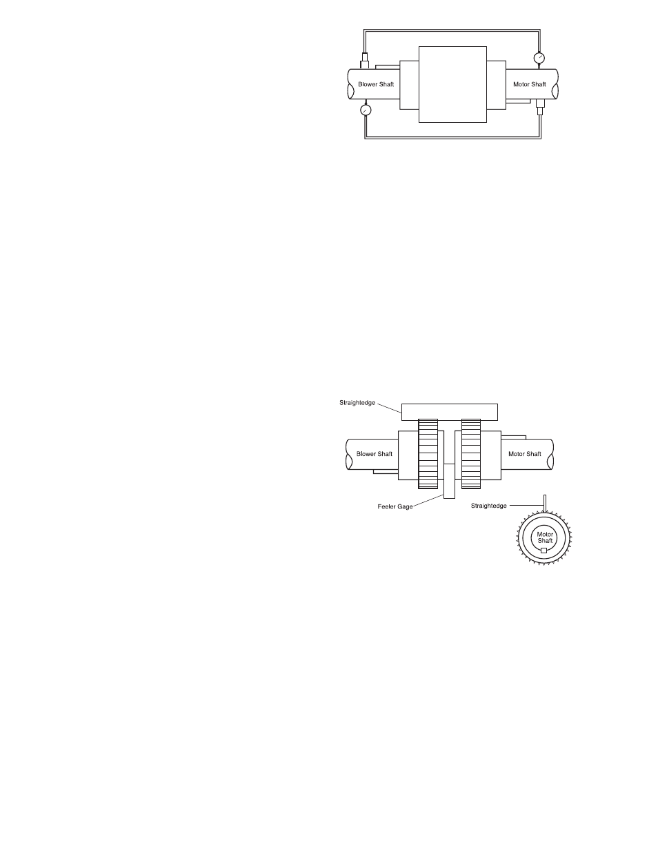
Reverse Indicator Method (Permissible)
This method may be done electronically following
the instrument manufacturer's instructions or by
means of dial indicators as follows:
1. Reinstall the coupling sleeve, seal and snap ring.
2. Clamp dial indicators on shafts 180° apart as
shown.
3. Place indicator probes on opposite shafts as
shown.
4. Rotate both shafts simultaneously in the correct
operating direction, taking readings at 90°
intervals.
5. Adjust motor to achieve parallel and angular
alignment. If questions arise, contact the Spencer
Service Department.
Straightedge Method (Permissible)
1. Remove old lubricant and clean the hub teeth.
2. Set a machine shop quality straightedge across
the coupling hubs (at the root diameter of the
gear teeth).
3. Adjust the motor so the straightedge is evenly
supported between the coupling hubs at the 3, 6,
9 and 12 o'clock positions.
4. Using a feeler gage, measure the clearance
between the coupling hubs at the 3, 6, 9 and 12
o'clock positions.
5. Adjust the motor so the gap is identical at all four
positions and in accord with the table of hub to
hub gaps.
4
The Spencer Turbine Company ◆ 600 Day Hill Road, Windsor, CT 06095 ◆ TEL 800-232-4321 ◆ 860-688-8361 ◆ www.spencerturbine.com