Spencer Single-Stage Scroll Blowers User Manual
Page 3
3
The Spencer Turbine Company ◆ 600 Day Hill Road, Windsor, CT 06095 ◆ TEL 800-232-4321 ◆ 860-688-8361 ◆ www.spencerturbine.com
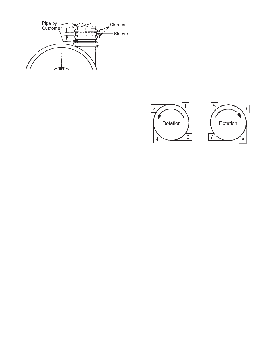
The rubber connecting sleeve supplied with the scroll
should be installed so that it covers a gap of
approximately one inch as illustrated. The mounting
clamps supplied with the sleeve should be
adequately tightened to effect an air-tight connection.
Electrical
Caution: Be sure motor, starter, controls and
other electrical equipment is the proper type
suitable for the application and environment and
complies with all applicable codes.
Be sure that the motor furnished with this machine is
wound for the same type of voltage available at the
installation site. In making the electrical connections,
follow the wiring instructions furnished. Wire and
fuses should be of ample capacity to insure that
proper voltage is maintained at the motor terminals
while starting and running. It is important that proper
starting equipment be used. All AC machines should
be equipped with a magnetic contactor or a manual
or automatic compensator depending on the machine
size and the installation regulations of the local
power company. The starters should have thermal
overload protection as well as true low-voltage
protection.
Air Filters
The Spencer Turbine Company recommends the
use of inlet air filters on all Scroll Blowers for
pressure applications.
The use of any type of filter requires that it
be kept
clean to prevent excessive pressure drop in the
lines. The dry element of the Spencer filter may be
cleaned with soap & water and reused.
Silencers and Combination Filter-Silencers
Spencer offers silencers and combination filter-
silencers for intake discharge, and bleed applications.
The silencers should be properly supported at both
ends. Rigid connection to the machine is not
recommended. The tubing mount is recommended
and connects to the machine with a rubber sleeve
and a flange to tubing adapter.
This diagram shows the available discharge
positions, viewed from the intake end, and the
direction of blower rotation associated with each
discharge position.
Coupling Alignment
The coupling on this machine was carefully aligned
at the factory and the coupling halves and shell(s)
marked to indicate optimum relative position.
However, transportation may have caused coupling
misalignment.
Caution: Check the motor and blower shafts for
misalignment and carefully realign them if
necessary after Installation and before startup,
as misalignment can cause destructive vibration.
Coupling alignment should be rechecked again
after an hour's operation. Final alignment should
be made at average operating temperature. After
each alignment check, add lubricant per
instructions and replace coupling guard.
WARNING: DISCONNECT AND LOCK OUT
ELECTRICAL POWER BEFORE PERFORMING
ALIGNMENT.
On certain blowers, the coupling is disassembled after
factory alignment and marking. The coupling halves
are specially protected against the elements during
shipping. Prior to startup, assemble the coupling,
align keyways using factory markings and lubricate
as instructed.
Rubber Inlet and Outlet Sleeve
Vacuum Applications
When the machine is used for vacuum, the outlet
should discharge outdoors (preferred) or into a room
having ample volume and proper ventilation in order
to permit the air to escape and at the same time
keep the unit at a reasonable temperature. Intake air
must be kept clean through proper filtration methods.
Motor Rotation
The motor must be wired correctly to rotate the
blower in the right direction. A rotation arrow is
located on the blower housing. "Bump" or jog the
start button and observe the direction of rotation of
the motor shaft. This movement must agree with the
rotation arrow. If the rotation is incorrect, the motor
wiring must be changed.