Gotham ROUGH-IN SECTION FOR DPH User Manual
Page 2
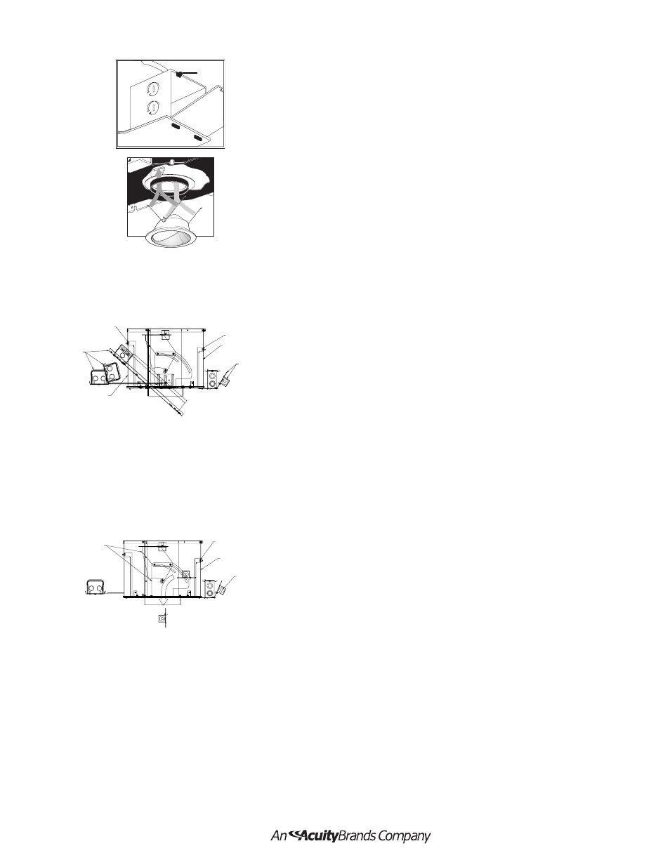
FEED WIRE CONNECTION TO FIXTURE JUNCTION BOX Refer to Figure 3.
J-box is approved for through wiring with 4 No. 12 AWG in and out. Six 1/2” or
three 3/4” knockouts are available. Use feed wire with insulation rated 90° C
or higher.
1. Remove j-box cover by releasing spring clip (A) at top and allowing cover
(B) to hinge open.
2. Select knockout, remove, and install appropriate box connector.
3. Install feed wire applicable to NEC and/or local requirements.
4. Connect the hot to the black and neutral to white insulated wires provided
in the j-box. There is a green GROUNDING screw with washer located in the
bottom of the box.
5. Reinstall junction box cover (B) and the wiring is complete.
BALLAST REPLACEMENT Refer to Figure 5.
1. Remove lamp and trim from fixture.
2. Rotate adjustment mechanism to allow access to ballast access door and
j-box access door.
3. Loosen the knurled screw that can be seen through the aperture.
4. Slide ballast access and j-box access doors to the side.
5. Remove outside j-box door with thermal protector attached. Reach through
aperture and ballast access. Grab ballast and rotate toward aperture to
detach from ballast rails. Slide ballast assembly through ballast access and
aperture.
6. Install replacement in reverse order.
7. Replace lamp and trim.
INSULATION DETECTOR REPLACEMENT Refer to Figure 6.
1. Remove lamp and trim from fixture.
2. Rotate adjustment mechanism to allow access to ballast access door and
j-box access door.
3. Reach through aperture and disengage outside j-box cover by pulling up
on spring retainer.
4. Pull j-box door and top down assembly through aperture. Disconnect wires
at wire nuts and remove from housing.
5. Install replacement in reverse order.
6. Replace lamp and trim.
Figure 3
Figure 4
Part No. CJ520661
8/02
Thumb Screw
Ballast
Assembly
Ballast
Access
Door
J-box Access
Door
Thermal
Protector
Assembly
Thumb Screw
Thumb Screw
J-box Access
Door
Thermal
Protector
Assembly
Adjustment
Mechanism
Figure 5
Figure 6
A
B