Fixture connections and hanging instructions – Gotham PDPH Elevations User Manual
Page 2
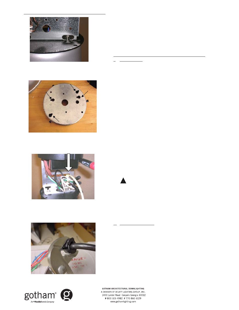
Figure 1B-2
Figure 1C
Figure 2C
Figure 1D
14. Attach the safety chain hook to an open hole to secure and
suspend the entire assembly. Make power and ground connec-
tions. For EL, cap the unused 120V or 277V line from the canopy and
connect the battery activation leads (small red and white wires).
15. Position the complete assembly to align the "V" notch on the
canopy with the "V" notch on the mounting pan. Tuck in all wires,
close assembly to mounting pan and twist to engage screws into L-
slots (See Figure 1D).
16. Tighten screws. INSTALLATION COMPLETE.
Cord Mount (Emergency PDPF and Standard PDPH)
I.
Ground Prep
1. Temporarily remove top cap and any round decorative piece to ex-
pose support bracket.
2. Removing socket assembly from box, attach socket cup to reflector
(per trim instructions).
3. Route socket wires through housing and bundle wires underneath
the L-shaped support bracket. Do NOT pass wires through the
bracket center .875 hole.
4. Replace the top cap and round decorative piece, leaving screws
loose for later steps.
5. Measure desired hanging length from ceiling to top of fixture, then
subtract the thickness of the canopy and add 6 inches. **Ceiling
suspension length - canopy thickness + 6 inches = cord length.**
6. Strip off 4 inches of cord jacket to expose inner conductors and
strip 1/2 in. from each conductor to expose copper.
7. Secure the provided strain relief bushing a minimum of 2 inches
above the stripped edge of the cord. Use pliers or vice grips to
crimp around the cord jacket - flat side facing up. IF ADJUST-
MENT IS REQUIRED, USE FLATHEAD SCREWDRIVER TO PRY OFF
BUSHING AND RECRIMP, OR CUT BUSHING OFF AND USE
EXTRA ONE PROVIDED (See Figure 2C).
8. Remove the fixture cap to expose support bracket and route cord
through top center hole.
9. VERIFY CORD IS ROUTED THROUGH CAP AND ANY ROUND
DECORATIVE PIECES ARE ON FIXTURE! Align cord attached
bushing to bracket hole and press firmly into support bracket until
all three snaps engage. Flat ledge of bushing should sit flush with
bracket surface.
10.
!
WARNING! Possible falling hazard and risk of serious injury.
Gather both cord and socket leads into tie strap strain relief so that
a minimum of two inches of cord conductors with socket conduc-
tors are pulled inside tie strap. Pull tie strap tight enough to strain
relieve all connections. Trim excess strap material (See Figure 1B).
Make necessary conductor connections between ballast, socket
and ground wires using wire nuts.
11. Separate j-box mounting pan from top of canopy by loosening the 3
side screws, twisting and removing.
II. Ceiling Installation
12. Hang mounting pan by routing j-box wires through back of pan,
and using either 3.5 in. or 4.5 in. keyholes, secure to j-box (See
Figure 1C).
13. Attach safety chain hook to an open hole to secure and suspend
the entire assembly. Make power and ground connections using
wire nuts. For EL, cap the unused 120V or 277V line from the canopy
and connect the battery activation leads (small red and white
wires).
14. Align the "V" notch on the outer canopy with the "V" notch inside
the mounting pan. Tuck in all wires, close assembly to mounting
pan and twist to engage screws into L-slots (See Figure 1D).
15. Tighten screws. INSTALLATION COMPLETE.
Fixture connections and hanging instructions
3
1/2
3
1/2
4
1/2
4
1/2
Part No. CJ52007
©2005 Gotham
Rev. B 11/07
Elevations
®
- Part II