Gotham 4 Elevations PAR - PDPA & PDPH User Manual
Page 2
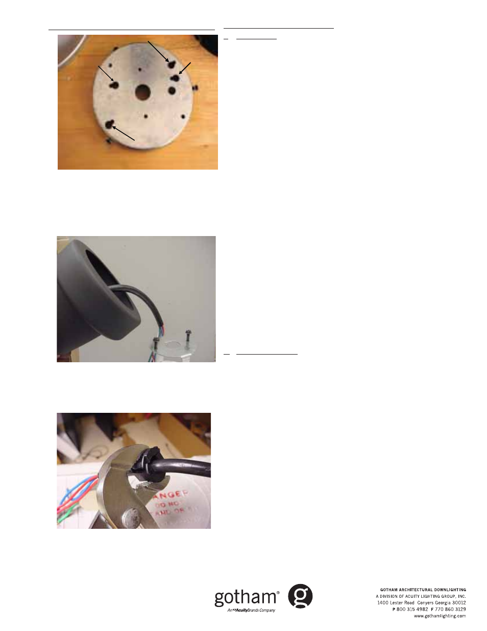
Figure 1D
Cord Mount -4" Elevations
TM
I
.
Ground Prep
1.
Temporarily remove top cap and any round decorative piece to
expose mounting holes and screws.
2.
Remove socket assembly from box, attach socket cup to reflector slots
3.
Route socket wires through housing PRIOR to installing reflector.
4.
Press reflector into housing until clips engage and flange is flush with
bottom of housing.
5.
Bundle wires above reflector inside housing (do NOT pass wires through
top hole).
6.
Replace the top cap and round decorative piece, leaving screws loose
for later steps.
7.
Measure desired hanging length from ceiling to top of fixture, then
subtract the thickness of the canopy and add 6 inches. **Desired
suspension length - canopy thickness + 6 inches=cord length.** Cut
cord to calculated length.
8.
Strip off 4 inches of cord jacket to expose inner conductors. Strip ½ inch
from each conductor to expose copper.
9.
Secure the provided strain relief bushing with a minimum of 2 inches
above the stripped edge of the cord. Use pliers or vice-grips to crimp
around the cord jacket – flat side facing up. IF ADJUSTMENT IS
REQUIRED, USE EITHER A FLATHEAD SCREW DRIVER TO PRY-OFF
BUSHING AND RECRIMP, OR CUT BUSHING OFF AND USE EXTRA ONE
PROVIDED (Figure 2B).
10. Remove the fixture cap to expose support bracket and to route cord
through top center hole.
11. VERIFY CORD IS ROUTED THROUGH CAP AND ANY ROUND DECORA-
TIVE PIECES. Align crimped bushing inside top hole of housing, and
press firmly to engage snaps and suspend fixture (Figure 2A).
12. Gather both cord and socket leads, and strain-relieve a minimum of 2
inches of cord conductors with socket conductors, using the provided
wire tie. Make connections with wire-nuts.
13. From canopy ASM, separate mounting pan by loosening 3 side screws
and twisting out of ceiling canopy part.
II. Ceiling Installation
14. Hang mounting pan by routing J-box wires through back of pan, and
using either 3.5 or 4.5 inch key holes, secure to J-box (Figure 1D).
15. With fixture suspended on cord, make power connections using wire
nuts.
16. Tuck in all wires, close assembly to mounting pan and twist to engage
screws into L-slots.
17. Tighten screws. INSTALLATION COMPLETE.
Fixture connections and hanging instructions
Part No.CJ520705
©2006 Gotham Rev. B
6/07
4" Elevations
TM
Page 2 of 2
Figure 2A
Figure 2B
3
1/2
3
1/2
4
1/2
4
1/2