5 inch spaced keyholes – Gotham PDPH GRS Recessed Mount User Manual
Page 2
Part No. CJ520709
02/07
Page 2 of 2
GRS Recessed Mount PDPA/PDPF/PDPH Installation Instructions
T
R
A
H
C
G
N
I
T
O
O
H
S
E
L
B
U
O
R
T
n
i
m
e
l
b
o
r
p
e
h
t
e
t
a
c
o
l
,
n
o
i
t
i
d
n
o
c
d
o
o
g
n
i
m
e
e
s
y
e
h
t
f
I
.
e
l
u
d
o
m
n
i
-
e
m
a
r
f
r
o
p
m
a
l
e
h
t
o
t
e
g
a
m
a
d
e
l
b
i
s
i
v
y
n
a
r
o
f
k
c
e
h
C
.
s
n
o
i
t
c
a
e
v
i
t
c
e
r
r
o
c
d
n
a
s
e
s
u
a
c
e
l
b
i
s
s
o
p
f
o
t
s
i
l
g
n
i
w
o
l
l
o
f
e
h
t
m
o
t
p
m
y
S
e
s
u
a
C
e
l
b
i
s
s
o
P
n
o
i
t
c
A
e
v
i
t
c
e
r
r
o
C
O
T
S
L
I
A
F
P
M
A
L
T
H
G
I
L
d
e
z
i
g
r
e
n
e
t
o
n
e
r
u
t
x
i
f
e
h
t
g
n
i
d
e
e
f
t
i
u
c
r
i
C
·
n
o
i
t
c
e
n
n
o
c
e
l
u
d
o
m
r
o
t
i
u
c
r
i
c
n
i
r
o
r
r
e
g
n
i
r
i
W
·
p
m
a
l
y
t
l
u
a
F
·
t
u
p
t
u
o
t
s
a
l
l
a
b
r
o
e
n
i
L
·
t
u
o
d
e
n
r
u
b
t
s
a
l
l
a
B
·
w
o
l
o
o
t
e
r
u
t
a
r
e
p
m
e
t
t
n
e
i
b
m
A
·
.
d
e
z
i
g
r
e
n
e
s
i
t
i
u
c
r
i
c
t
a
h
t
e
r
u
s
n
e
o
t
e
s
u
f
r
o
r
e
k
a
e
r
b
t
i
u
c
r
i
c
k
c
e
h
C
·
e
r
a
s
n
o
i
t
c
e
n
n
o
c
t
a
h
t
e
r
u
s
n
e
o
t
x
o
b
e
c
i
l
p
s
e
r
u
t
x
i
f
e
n
i
m
a
x
E
·
.
t
c
e
r
r
o
c
y
l
b
a
r
e
f
e
r
p
,
p
m
a
l
r
e
h
t
o
n
a
e
t
u
t
i
t
s
b
u
s
d
n
a
p
m
a
l
y
t
l
u
a
f
e
h
t
e
v
o
m
e
R
·
l
a
n
i
g
i
r
o
e
h
t
e
c
a
l
p
e
r
,
s
t
h
g
i
l
p
m
a
l
e
h
t
f
I
.
t
h
g
i
l
o
t
n
w
o
n
k
s
i
t
a
h
t
e
n
o
.
e
n
o
w
e
n
a
h
t
i
w
.
e
g
a
t
l
o
v
t
i
u
c
r
i
c
n
e
p
o
k
c
e
h
C
.
e
r
u
t
x
i
f
t
a
e
g
a
t
l
o
v
e
n
i
l
k
c
e
h
C
·
.
y
t
i
u
n
i
t
n
o
c
t
i
u
c
r
i
c
k
c
e
h
C
·
.
s
n
o
i
t
i
d
n
o
c
l
a
t
n
e
m
n
o
r
i
v
n
e
g
n
i
t
s
i
x
e
t
s
n
i
a
g
a
g
n
i
t
a
r
t
s
a
l
l
a
b
k
c
e
h
C
·
T
U
O
S
E
O
G
P
M
A
L
G
N
I
T
H
G
I
L
R
E
T
F
A
p
m
a
l
y
t
l
u
a
F
·
n
a
h
t
r
e
h
t
a
r
m
o
t
p
m
y
s
s
i
h
t
t
i
b
i
h
x
e
l
l
i
w
p
m
a
l
a
y
l
l
a
n
o
i
s
a
c
c
O
·
.
p
m
a
l
w
e
n
a
e
t
u
t
i
t
s
b
u
S
.
t
h
g
i
l
o
t
g
n
i
l
i
a
f
y
l
p
m
i
s
N
O
S
E
L
C
Y
C
P
M
A
L
F
F
O
D
N
A
e
r
u
t
x
i
f
o
t
e
s
o
l
c
o
o
t
s
i
n
o
i
t
a
l
u
s
n
I
·
h
g
i
h
o
o
t
e
g
a
t
t
a
w
p
m
a
L
·
w
o
l
e
g
a
t
l
o
v
t
u
p
t
u
o
t
s
a
l
l
a
B
·
)
"
3
t
s
a
e
l
t
a
(
e
l
u
d
o
m
d
n
u
o
r
a
m
o
r
f
n
o
i
t
a
l
u
s
n
i
e
v
o
m
e
R
·
.
g
n
i
s
u
o
h
n
i
d
e
i
f
i
c
e
p
s
e
g
a
t
t
a
w
p
m
a
l
l
l
a
t
s
n
I
·
.
e
g
a
t
l
o
v
t
i
u
c
r
i
c
n
e
p
o
k
c
e
h
C
.
e
r
u
t
x
i
f
e
h
t
t
a
e
g
a
t
l
o
v
e
n
i
l
k
c
e
h
C
·
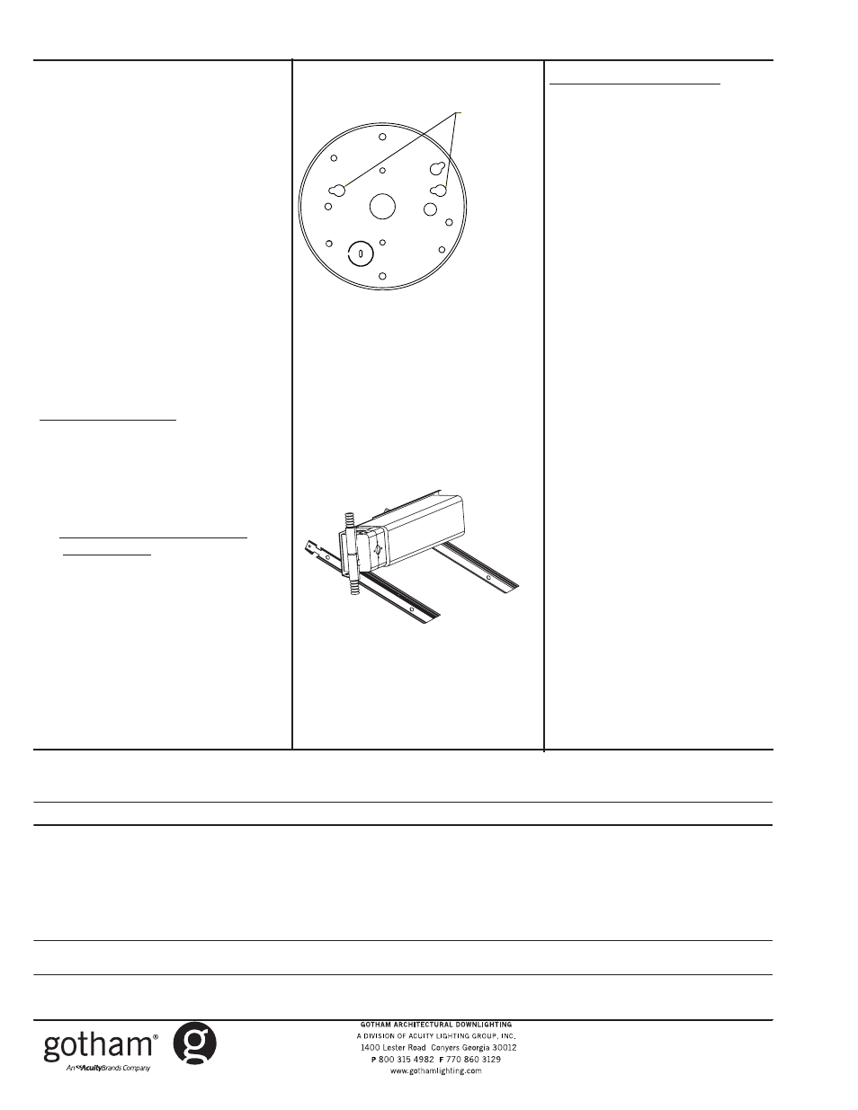
9. Connect flex to back of mounting
pan with end connector. Secure
flex with nut on inside of pan. Wires
should be inside of pan.
10. Orientate pan’s 3-1/2” spaced key-
holes with screws on mounting
bracket (Pan View).
11. Insert screws into pan keyhole
slots, and shift pan sideways to seat
into slots.
12. Tighten screws in slots to capture
pan to frame assembly. Make sure
screws are seated properly to cen-
ter pan.
13. Once pan is secured and centered,
installation of frame ASM is complete.
14. Mount canopy ASM per installation
instructions.
NEW INSTALLATION FOR GRS
Non-accessible ceiling (plaster, dry-
wall, etc.):
1. Release clamping latch arms and
adjust channel bars to the correct
spacing between joists as shown in
Figure 1.
2. Mounting Channel Bar- Flexible
Wiring Method
Bend ends of channel bars 90
° and
adjustment at its lowest point on the
mounting frame. Make sure bottom
of the flange is flush with the bottom
of the joists. Secure mounting frame
into position by closing the clamping
latch arm. Channel bars will accom-
modate mount to joists with vertical
up to 24” O.C. joists
Non-Flexible Wiring Method
If non-flexible wiring methods are
used follow procedure for flexible
wiring methods. Then lower mounting
frame equal to the thickness of the
finished ceiling or slightly above.
3. Remove knockouts on junction box
to feed power supply to fixture.
Supply wire must meet applicable
electrical codes and be rated for a
minimum of 75°C. Junction box is
thru-wire rated for 8-No. 12 AWG
conductors (4 in - 4 out).
4. Complete necessary wire connec-
tions. Snap the door onto junction
box. Note 1. For fluorescent appli-
cations. Dimming- Make necess-
ary wire connections per ballast
type. EL HID F-can- Allow for 9-1/2”
head space above for ballast
maintenance. Pivot ballast tray
onto spacer brackets as shown in
Figure 5. Thermal protector assem-
bly must be plugged into the
appropriate power supply voltage
(120V, 277V or 347V). Snap door onto
junction box.
Note 2. For incandescent 277V SDT
applications, make a minimum of 9-
1/2” head space available for yoke
height.
5. Follow steps 6-14 in previous
section.
Ballast Access: To access ballast
and/or J-box, first remove canopy
assembly from mounting bracket.
Remove mounting bracket and reach
through aperture to access J-box and
ballast
.
3.5 INCH SPACED
KEYHOLES
BACK OF MOUNTING PAN VIEW
Figure 4
Figure 5
CJ520709
Back of Mounting Pan View
3.5 Inch Spaced
Keyholes