Gotham SQDLV ADJ Mounting Frame User Manual
Page 2
SQDP, SQDPH, SQDTH, SQDLV ADJ Mounting Frame Installation Instructions
ACCESSING JUNCTION BOX FROM BELOW FOR
REPLACING BALLAST AND THERMAL
PROTECTOR
To gain access to junction box from below ceiling.
1. Remove trim.
2. Adjust lamp mounting bracket allowing access to
door, loosen thumb screw to remove door from
housing and set aside (see Figure 6).
AIMING LAMPS
SQDP, SQDPH, SQDTH housings
1. Remove trim.
2. Loosen wing nut securing lamp mounting bracket
in place, adjust to desired vertical position and
retighten (see Figure 7).
3. Loosen thumb screw securing lamp mounting
bracket to top of housing, adjust to desired horizontal
position and retighten (see Figure 7).
4. Reinstall trim.
SQDLV ADJ housings
1. Remove trim.
2. Loosen wing nut securing lamp mounting bracket
in place, adjust to desired vertical position and
retighten (see Figure 8).
3. Loosen wing nut securing lamp mounting bracket
to top of housing, adjust to desired horizontal position
and retighten (see Figure 8).
4. Reinstall trim.
POST INSTALLATION HOUSING ALIGNMENT
In the event that the trim is in need of alignment after
installation, adjustments can be made to the housing.
1. Remove trim by gripping edge of flange and pulling
it out of housing.
2. To adjust housing for trim alignment, reach through
aperture and loosen two speed nuts. Adjust housing
as required and retighten nuts (see Figure 9).
3. Reinstall trim.
NEW INSTALLATION FOR SQ SERIES
Non-accessible ceiling (plaster, drywall, etc.):
1. Release clamping latch arms and adjust
channel bars to the correct spacing between joists
(see Figure 1).
Mounting Channel Bar-Flexible Wiring Method
2. Bend ends of channel bars 90° and adjustment
at its lowest point on the mounting frame. Make
sure bottom of the flange is flush with the bottom of
the joists. Secure mounting frame into position by
closing the clamping latch arm. Channel bars will
accommodate up to 24” O.C. joists. The notch
located in the draw-down flange of the housing can
be used to assist with alignment of multiple
fixtures.
Non-Flexible Wiring Method
If non-flexible wiring methods are used, follow
procedure for Flexible Wiring Method, then lower
mounting frame equal to the thickness of the
finished ceiling or slightly above (1/8” max. – see
Figure 3). The notch located in the draw-down
flange of the housing can be used to assist with
alignment of multiple fixtures.
3. Remove knockouts on junction box to feed
power supply to fixture (see Figure 5). Supply wire
must meet applicable electrical codes and be rated
for a minimum of 90°C. Junction box is thru-wire
rated for 8-No. 12 AWG conductors(4in- 4out).
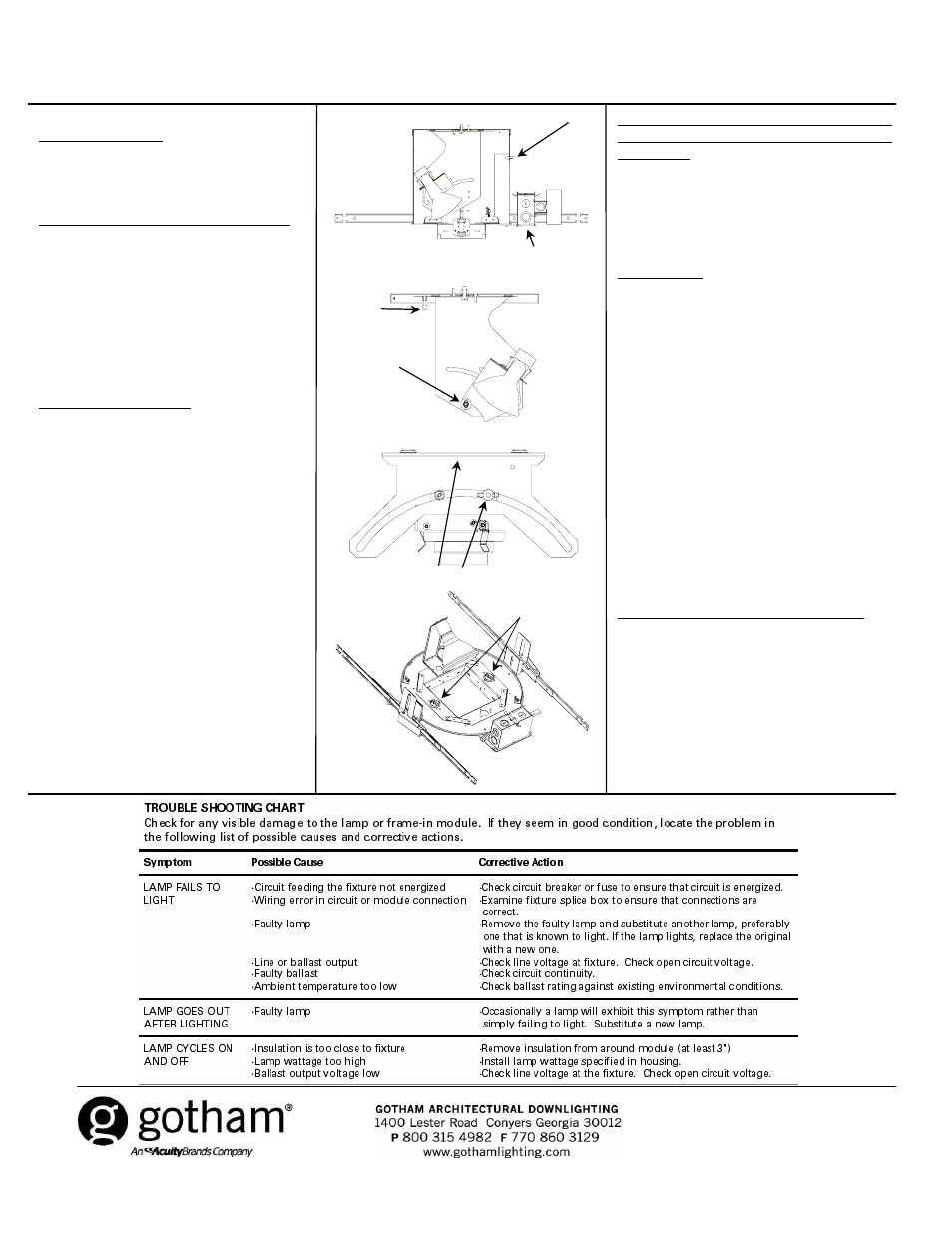
Figure 6
Figure 7
Figure 8
Thumb screw
Wing nut
Wing nuts
Junction box
Speed nuts
Figure 9
(located in center of assembly)
Thumb screw
CJ5200904 Rev. A
1/10 2 of 2
©2009 Acuity Brands Lighting, Inc.
All Rights Reserved.