Save these instructions – Gotham LGI Renovation User Manual
Page 3
CJ5201014 Rev. D
2/2014 3 of 6
©2010, 2011 Acuity Brands Lighting, Inc.
All Rights Reserved.
SAVE THESE INSTRUCTIONS
Upon receipt, thoroughly inspect for any
freight damage which should be brought
to the attention of the delivery carrier.
Compare the catalog description listed on
the packing slip with the label on the
carton to ensure you have received the
correct merchandise.
INSTALLATION INSTRUCTIONS
AFI/AFVI/LGFI/LGFVI/PDGFI
PDXFI/PDTFI/AHI/LGHI/AII/LGI
Renovation
IMPORTANT SAFETY INFORMATION
For Your Protection, Read Carefully
Warning: Risk of fire. Do not install
insulation within 3 inches of fixture
sides or wiring compartment, nor above
fixture in such a manner as to entrap
heat.
1. Electric current can cause painful
shock or serious injury unless handled
properly. For your safety, always
remember the following:
• Turn off the supply power.
• Ground the fixture to avoid potential
electrical shocks.
• Do not handle an energized fixture or
energize any fixture with wet hands,
when standing on a wet or damp surface,
or in water
2.
Specific
safety
information
concerning lamps:
• Match wattage of fixture and lamp
exactly.
• Do not remove or insert lamp when
power is on.
• Do not scratch glass or subject lamp to
undue pressure as either may cause
lamp breakage.
• Protect operating lamp from sources of
moisture.
• If lamp is marked
it contains
mercury. Follow disposal laws. See:
www.lamprecycle.org.
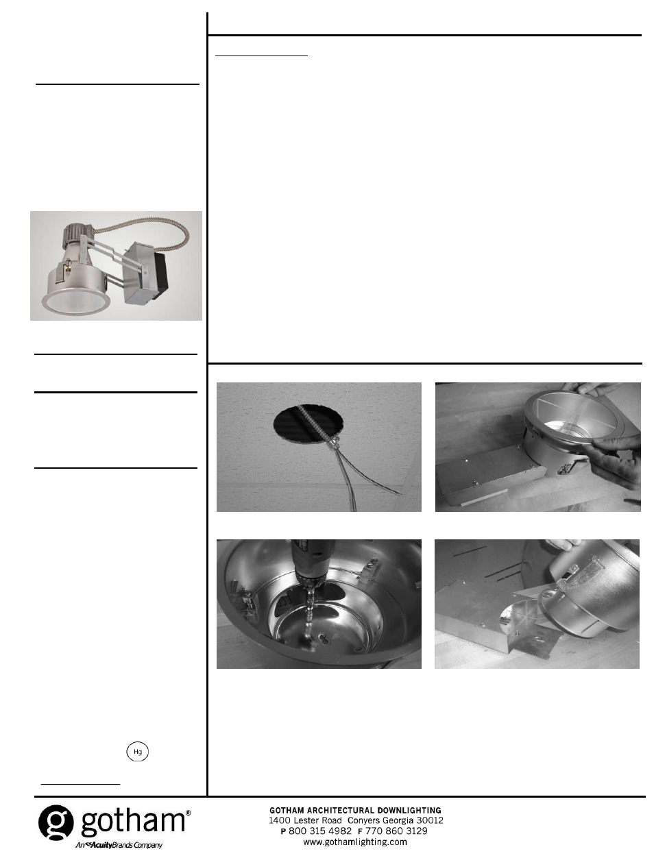
NEW INSTALLATION
1. Cut ceiling opening (6” fixture = 6-7/8”, 8” fixture = 8-5/8”).
2. Pull electrical leads through opening as shown in Figure 1. Supply wire must meet applicable
electrical codes and be rated for a minimum of 90°C.
3. Remove finishing trim from housing/socket assembly and set aside as shown in Figure 2.
4. For horizontally lamped fixtures, loosen screw holding upper reflector to socket housing/junction
box and remove as shown in Figure 3a and 3b.
5. Remove cover from socket housing/junction box to access wire compartment as shown in Figure
4a or 4b.
6. Connect flexible conduit to socket housing/junction box as shown in Figure 5. Ensure connection
between flexible conduit and socket housing/junction box is secure.
7. Make wire connections.
8. Reinstall socket housing/junction box cover plate.
9. Attach upper reflector to socket housing/junction box and tighten screws.
10. Install housing assembly through opening in ceiling as shown in Figure 6a or 6b.
11. Ensure junction box has rotated downward to rest on ceiling (not on rafters, joists, braces or
the like).
12. Secure housing assembly by tightening (3) swing gates until flange is tight against ceiling
as shown in Figure 7.
13. Install lamp, supplied by others (refer to label located inside reflector or near socket for proper
lamp type/wattage).
14. Install finishing trim as shown in Figure 8.
Figure 1
Figure 2
Figure 3a
Figure 3b