Gotham Yoke User Manual
Save these instructions
INSTALLATION INSTRUCTIONS
Yoke
Upon receipt, thoroughly inspect for any
freight damage which should be brought to
the attention of the delivery carrier. Compare
the catalog description listed on the packing
slip with the label on the carton to ensure
that you have received the correct
merchandise.
IMPORTANT SAFETY INFORMATION
For Your Protection, Read Carefully
Warning: Risk of fire. Do not install
insulation within 3 inches of fixture
sides or wiring compartment, nor above
fixture in such a manner as to entrap
heat.
1. Electric current can cause painful
shock or serious injury unless
handled properly. For you safety,
always remember the following:
• Turn off the supply power.
• Ground the fixture to avoid
potential electrical shocks.
• Do not handle an energized
fixture or energize any fixture with
wet hands, when standing on a
wet or damp surface, or in water.
2. Specific
safety
information
concerning lamps:
• Match wattage of fixture and lamp
exactly.
• Do not remove or insert lamp
when power is on.
• Do not scratch glass or subject
lamp to undue pressure as either
may cause lamp breakage.
• Protect operating lamp from
sources of moisture.
• If lamp is marked
it
contains mercury. Follow disposal
laws. See: www.lamprecycle.org.
SAVE THESE INSTRUCTIONS
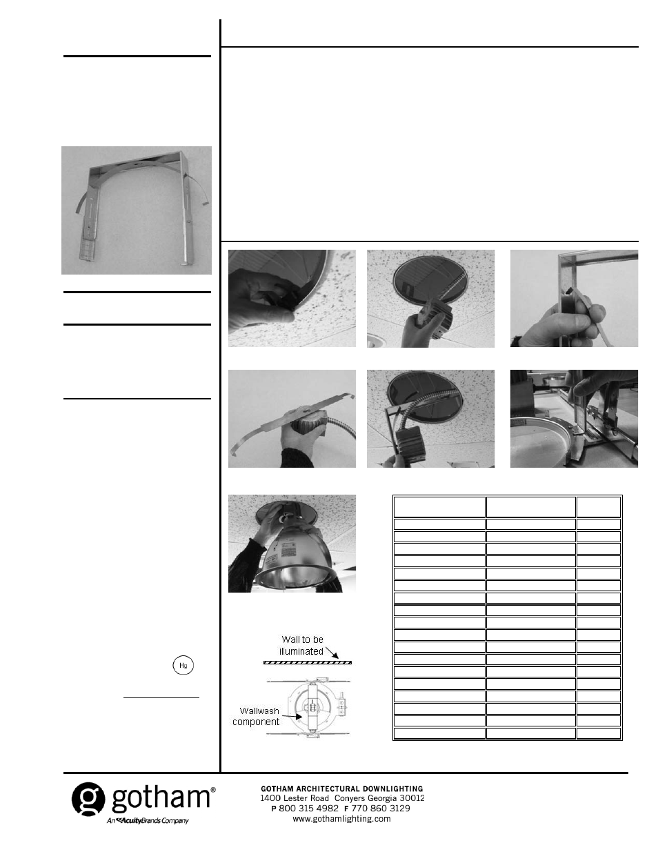
1. Remove clips from mounting frame for all
reflector types except APR (see Figure 1).
2. Pull socket cup included with mounting frame
through ceiling opening (see Figure 2).
3. Remove bow spring from yoke assembly by
pulling the ends of the spring through the slots in
the uprights (see Figure 3).
4. With the curve of the bow spring facing
downward, attach it to the top of the socket cup
by inserting screw located in the top of the socket
cup into the
keyhole slot in the spring. Engage
screw in slot and tighten it securely (see
Figure
4).
5. Reinsert ends of bow spring into slots in uprights
(see Figure 3). See Figure 9 for correct slot
position.
6. Insert yoke assembly through ceiling opening
(see Figure 5).
7. Attach yoke assembly to mounting frame by
inserting feet into raised tabs (see Figure 6). Feet
will snap into place.
8. Pull the socket cup down into the ceiling opening
(see Figure 7) and attach to reflector (see
separate instruction sheet).
9. Push reflector up into ceiling opening making
sure that wallwash component (if present) is
properly oriented with respect to the wall to be
illuminated (see Figure 8).
10. If reflector does not rest tightly against ceiling,
remove the reflector, loosen screws in yoke
assembly, adjust
appropriately (see Figure 9),
tighten screws and re-attach reflector.
Figure 1
Figure 3
Figure 4
Figure 2
Figure 5
Figure 6
Figure 7
Figure 8
Trim Catalog No.
Distance from finished
ceiling to top of yoke (in.)
Slot
position
AFV/AFVW 4" TRT TRIM
9
Upper
AFV/AFVW 5" TRT TRIM
9 1/4
Upper
AFV/AFVW 6" TRT TRIM
9 3/4
Upper
AFV/AFVW 6" TRIM
10 3/4
Upper
AFV/AFVW 8" TRT TRIM
10 1/2
Upper
AFV/AFVW 8" TRIM
11 3/8
Upper
A/AW 4" TRIM
7 3/8
Lower
A/AW 6" TRIM
9 5/8
Upper
A/AW 8" TRIM
12
Upper
AH/AHW 4" TRIM
8 1/4
Upper
AH/AHW 6" TRIM
9 5/8
Upper
AH/AHW 8" TRIM
10 3/8
Upper
APR PAR20 4" TRIM
7 3/4
Lower
APR PAR30 4" TRIM
8 7/8
Upper
APR PAR30 6" TRIM
9 7/8
Upper
APR PAR38 6" TRIM
11 1/8
Upper
APR P36/AR111 6" TRIM
11 1/8
Upper
APR PAR38 8" TRIM
11 1/2
Upper
Figure 9
CJ520238 Rev. A
11/2007