Gotham 2 DLV Adjustable Pinhole SpecSheet User Manual
Page 3
© 2007-2013 Acuity Brands Lighting, Inc. All Rights Reserved. Rev.08/07/13. Specifications subject to change without notice.
PAGE 3 OF 3
DLV-2-ADJ-PInhOLE
PH
OTO
M
ET
RY
2” DLV
Adjustable Pinhole
Seamless Cast Faceplate with Open Cone, Max 75 Watt
PHOTOMETRY NOTES
•
Tested to current IES and NEMA standards under stabilized laboratory conditions.
•
Actual performance may differ as a result of end-user environment and application.
•
Consult factory or IES file for microgroove baffle, black cone or other photometric reports.
LAMP PERFORMANCE DATA
All data was calculated from each lamp manufacturer’s published data and is subject to normal lamp variations. Maximum footcandle is usually at the aiming point, but not
always on wider spread lamps. Lamp data supplied by manufacturers is approximate, and individual lamp performance may vary.
ACCENT LIGHTING ANGLE PERFORMANCE DATA
DISTANCE LAMP TO LIGHTED SURFACE
2 FEET
4 FEET
DISTANCE DOWN TO AIMING POINT
V1 (FT) 2
V2 (FT) 7
Beam
Lamp No.
Watts Type
MFG. Width (°) MBCP Aiming Angle Beam
Aiming Angle Beam
to
45°
Length Width
60°
Length Width
50% MBCP FT-CANDLES
FT-CANDLES
MR-16
ESX
20
NSP GE/SY/PH
15
3600
318
1.1
0.7
28
4.4
2.1
BAB
20
FL
GE/SY/PH
40
525
46
3.4
2.1
4
19.3
5.8
EXT
50
NSP GE/SY/PH
13
10200
902
0.9
0.6
80
3.8
1.8
EXZ
50
NFL
GE/SY
26
3400
301
2.0
1.3
27
8.8
3.7
EXN
50
FL
GE/SY/PH
40
1850
164
3.4
2.1
14
19.3
5.8
EYJ
71/65
MFL
GE/SY
24
4900
433
1.8
1.2
38
7.9
3.4
EYC
71/65
FL
GE/SY
36
2100
186
2.9
1.8
16
15.2
5.2
MR-11
FTB
20
SP
SY/PM
10
5000
442
0.7
0.5
39
2.9
1.4
FTD
20
NFL
SY/PM
30
600
53
2.3
1.5
5
10.9
4.3
FTE
35
SP
SY
10
6500
575
0.4
0.5
51
2.9
1.4
FTH
35
NFL
SY/PM
30
1300
115
2.3
1.5
10
10.9
4.3
ALR-12
GBD
20
NSP
PH
6
7000
619
0.4
0.3
55
1.7
0.8
GBE
20
SP
PH
18
1500
133
1.3
0.9
12
5.5
2.5
GBF
20
FL
PH
32
750
66
2.5
1.6
6
12.2
4.6
LOCATION OF ACCENT LUMINAIRE TO PROVIDE AIMING PT. 5.5' ABOVE THE FLOOR
Clg. Ht. (ft)
60° Aiming Angle
45° Aiming Angle
Out (H) Down (V2)
Out (H) Down (V1)
8
1.5
2.5
2.5 2.5
9
2.0
3.5
3.5 3.5
10
2.5
4.5
4.5 4.5
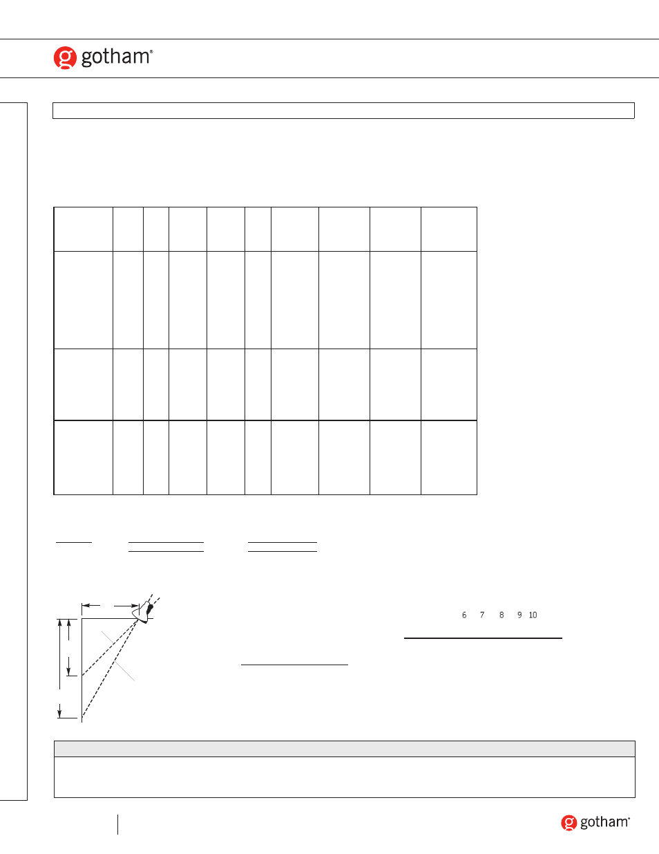
V1
V2
H
45˚
aiming
angle
60˚
aiming
angle
fc =
MBCP x Cos
3
(aiming angle)
H
2
(distance from wall squared)
Feet out
Aiming
angle Cos
3
Feet
down from ceiling (V)
45° .354
6
7
8
9 10
50° .266
7
8 10 11 12
55° .189
9 10 11 13 14
60° .125
10 12 14 16 17
65° .076
13 15 18 19 21
70° .040
17 19 22 25 28
75° .017
22 26 30 34 37
Formula for other distances and aiming angles.