Gotham ROUGH-IN SECTION for DLWH 6 & 8 User Manual
Page 2
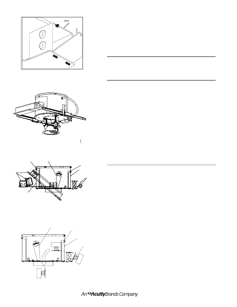
FEED WIRE CONNECTION TO FIXTURE J-BOX
Refer to Figure 5.
J-box is approved for through wiring with eight No. 12 AWG conductors
(4 in/4out) rated 90°C or higher.
1. Remove J-box cover by releasing spring clip (A) and allowing
cover (B) to hinge open.
2. Select knockout, remove, and install appropriate connector.
3. Install feed wire in accordance with and/or local electrical codes.
4. Complete wiring.
5. Reinstall J-box cover (B).
TRIM REMOVAL
1. Remove trim by gently pulling down until butterfly springs are visible.
Squeeze springs together to release from the slots provided in
the housing.
Refer to Figure 6.
1. Remove lamp and trim from fixture
2. Rotate adjustment mechanism (A) to allow access to
ballast access door (B) and J-box access door (C)
3. Loosen the thumb screws (D) that can be seen through
the aperture
4. Slide ballast access door (B) and J-box access door (C)
to the side.
5. Remove outside J-box door with thermal protector
attached (E). Unwire. Reach through aperture and ballast
access.
Grab ballast assembly (F) and rotate toward aperture to
detach from ballast rails. Slide ballast assembly (F)
through ballast access and aperture.
6. Install replacement in reverse order.
7. Replace lamp and trim.
ELECTRONIC BALLAST/INSULATION DETECTOR REPLACEMENT
Refer to Figure 8.
1. Remove lamp and trim from fixture.
2. Rotate adjustment mechanism (A) to allow access to
J-box access door (B).
3. Loosen the thumb screw (C) that can be seen through
the aperture.
4. Slide J-box access door (B) to the side.
5. Reach through aperture and disengage outside j-box
doorcover by pulling up on spring retainer.
6. Pull ballast assembly /insulation (D) detector through
aperture (Fig. 8). Disconnect wires and remove from
housing.
7. Install replacement in reverse order.
8. Replace lamp and trim.
Figure 5
Part No. CJ520667
7/06
Page 2 of 2
A
B
B
Figure 6
Figure 8
Figure 6
A
C
B
D
B
F
D
A
D
C
A
Figure 7
MAGNETIC BALLAST REPLACEMENT Refer to
Figure 7.