Gotham ROUGH-IN SECTION FOR ATH, DTH & DLWTH User Manual
Page 2
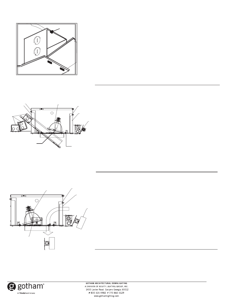
FEED WIRE CONNECTION TO FIXTURE J-BOX Refer to Figure 5.
J-box is approved for through wiring with eight No. 12 AWG 4 in and
4 out. Two 1/2” or three 3/4” knockouts are available. Use feed wire with
insulation rated 90
o
C or higher.
1. Remove J-box cover by releasing spring clip (A) allowing
cover (B) to hinge open.
2. Select knockout, remove and install appropriate box connector.
3. Install feed wire applicable to NEC and/or local requirements.
4. Install ballast assembly, first by connecting socket/plug assembly then
attach green ground wire to ground wire provided in junction box with
wire nut.
5. Complete wiring.
6. Snap ballast assembly onto junction box.
MAGNETIC BALLAST REPLACEMENT Refer to Figure 6.
1. Remove trim from fixture.
2. Rotate reflector yoke (A) to allow access to ballast
access door (B) and J-box access door (C). Remove upper reflector
by loosening two screws (G).
3. Loosen the thumb screws (D) that can be seen through the aperture.
4. Slide ballast access door (B) and J-box access door (C) to the side.
5. If ATH fixture, remove housing wrap by loosening the two wingnuts (H)
which are 180
o
apart. Set wrap aside.
6. Remove outside J-box door with thermal protector attached (E)
and unwire.
7. Grab ballast assembly (F) and rotate toward aperture to detach
from ballast rails. Slide ballast assembly (F) through ballast access
and aperture.
8. Install replacement in reverse order.
9. Replace upper reflector.
. Replace trim.
ELECTRONIC BALLAST/INSULATION DETECTOR REPLACEMENT
Refer to Figure 7.
1. Remove trim from fixture.
2. Rotate adjustment mechanism (A) to allow access to J-box access
door (B). Remove upper reflector by loosening two screws (E).
3. Loosen the thumb screw (C) that can be seen through the aperture
4. Slide J-box access door (B) to the side.
5. Reach through aperture and disengage outside j-box cover by
pulling up on spring retainer.
6. Pull ballast assembly/insulation detector (D) through aperture.
Disconnect wires and remove from housing.
7. Install replacement in reverse order.
8. Replace upper reflector.
9. Replace trim.
A
B
Figure 5
Figure 7
A
B
C
D
B
C
Figure 6
A
B
C
D
D
E
F
A
B
D
E
A
D
B
F
D
C
E
Part No. CJ520714
©2006 Gotham,10/06
H
10
G