Save these instructions – Gotham Decorative Rings_Disks User Manual
Page 3
CJ5201130 Rev. B
2/2014 3 of 4
©2011 Acuity Brands Lighting, Inc.
All Rights Reserved.
SAVE THESE INSTRUCTIONS
Upon receipt, thoroughly inspect for any
freight damage which should be brought
to the attention of the delivery carrier.
Compare the catalog description listed on
the packing slip with the label on the
carton to ensure you have received the
correct merchandise.
INSTALLATION INSTRUCTIONS
Decorative Rings/Disks
IMPORTANT SAFETY INFORMATION
For Your Protection, Read Carefully
Warning: Risk of fire. Do not install
insulation within 3 inches of fixture
sides or wiring compartment, nor above
fixture in such a manner as to entrap
heat.
Electric current can cause painful
shock or serious injury unless handled
properly. For your safety, always
remember the following:
• Turn off the supply power.
• Ground the fixture to avoid potential
electrical shocks.
• Do not handle an energized fixture or
energize any fixture with wet hands,
when standing on a wet or damp surface,
or in water
Installation DLD or DLR
1. This kit consists of a decorative lens, mounting hardware, threadlock and may include a yoke assembly.
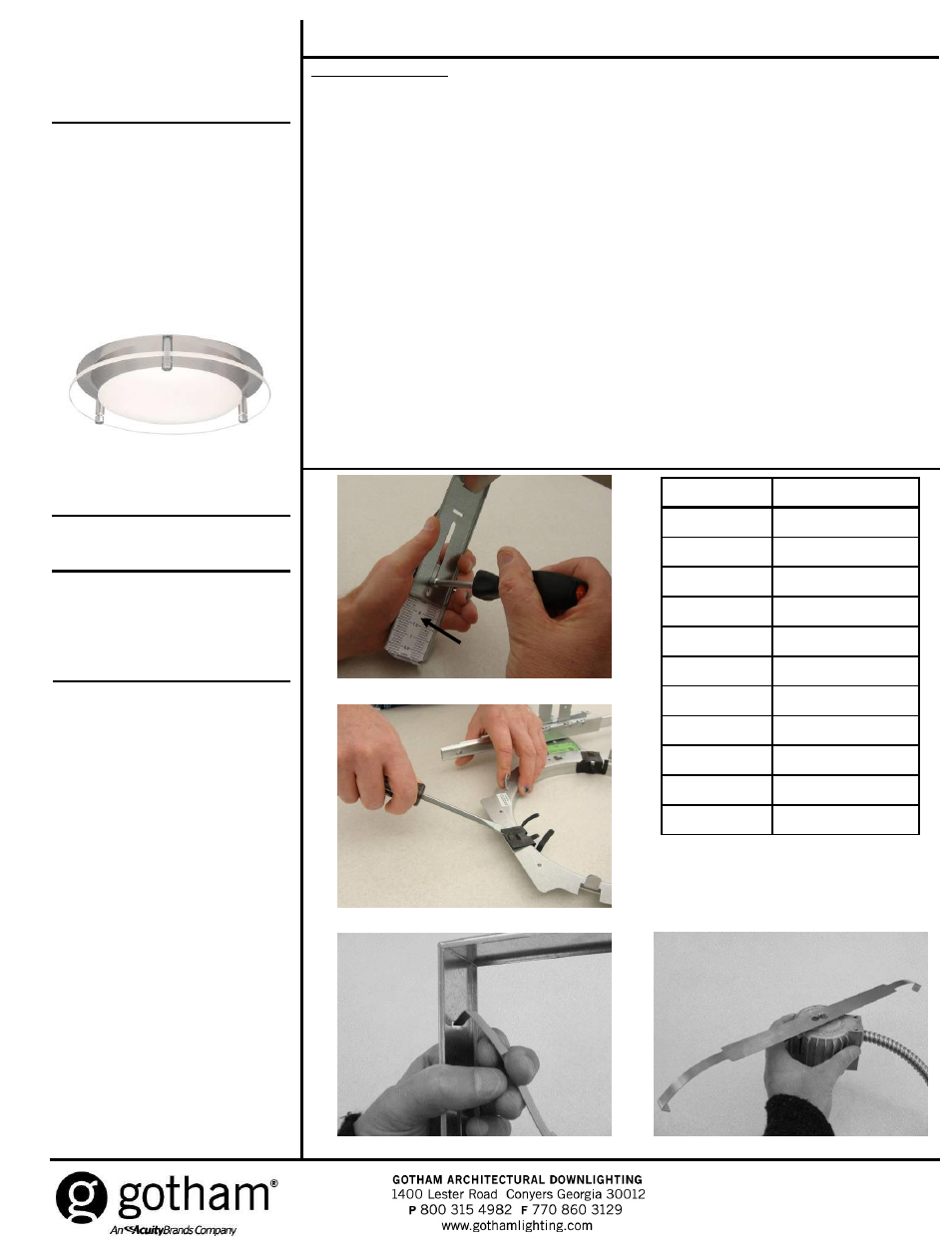
2. If yoke assembly is not included, proceed to step 8. If yoke assembly is included, adjust yoke using scale as
shown in Figure 1 to accommodate reflector type as shown in Table 1. Settings are based on ceiling thickness
of 7/8”. Adjust settings appropriately for ceiling thickness greater than 7/8”.
3. Remove clips from mounting frame using flathead screwdriver as shown in Figure 2.
4. Remove bow spring from yoke assembly by pulling the ends of the spring through the slots in the uprights as
shown in Figure 3.
5. With the curve of the bow spring facing downward, attach it to the top of the socket cup/light engine by inserting
screw located in the top of the socket cup/light engine into the keyhole slot in the spring. Engage screw in slot
and tighten it securely as shown in Figure 4.
6. Reinsert ends of bow spring into slots in uprights as shown in Figure 3.
7. Assemble yoke to mounting frame by snapping into frame tabs as shown in Figure 5.
8. Apply threadlock material to threaded studs on trim and install decorative studs included in hardware bag as
shown in Figure 6.
9. Pull the socket cup/light engine down into the ceiling opening and attach to trim, refer to separate instruction
sheet provided with trim for proper installation.
10. Push trim up into opening so flange is tight against ceiling.
11. Apply threadlock material to threads on each threaded stud and attach decorative lens to trim using decorative
hardware as shown in Figure 7.
12. Clean decorative element of any fingerprints or debris using a mild, non-abrasive dishwashing detergent in warm
water. Dry thoroughly using a lint free, non-abrasive cloth. Final assembly shown in Figure 8.
Figure 1
Yoke scale
Reflector Type
Yoke Scale Setting
AFV 6
2.5
AFV 6 TRT
1.7
AH 6
1.0
AH 6ARN
1.9
ALED 6
0.3
AFV 8
2.5
AFV 8 TRT
3.0
AH 8
1.5
AH 8ARN
2.6
ALED 8
1.5
Table 1
Figure 2
Figure 4
Figure 3