Extron Electronics TPT101_TPR101 User Guide User Manual
Page 8
6
TPT101 / TPR101 Operation Manual - Preliminary 8/18/2003
© 2003 - EXTRON, Inc.
It is imperative that the wired pairs in the TPT101 / TPR101 CAT5 system
adhere to the wiring standards shown on page 8, otherwise the system will
not function properly. The pertinent standard for INLINE’s CAT5 cable is
the TIA 568B. In order for the TPT101 / TPR101 system to function
properly, the CAT5 wire pairs (regardless of their color) must be
maintained within both RJ45 connectors.
5.) Set the sync mode switch on the back of the TPR101 as appropriate for the type of video
signal transmitted:
RGBHV / RGBS Computer Video Signals: Set the switch to SYNC SEP
RGsB Computer Video Signals / Composite / Y/C / Component Video Signals:
Set the switch to SYNC PASS.
6.) Connect the Display Device to the TPR101 15-pin VGA output port using an IN8000 /
IN800M Series VGA cable or an IN9045 Series 15-Pin HD Male to 5-BNC cable.
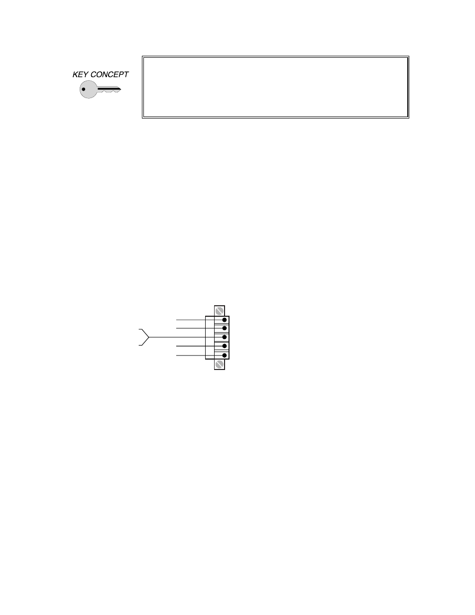
7.) For Applications with Audio Transmission - connect the audio cable to the appropriate pins
on the TPR101 5-pin captive screw terminal labeled Audio Output A. Make sure that the
stereo audio output is connected appropriately for a balanced audio signal as required by the
installation (see diagram below).
Note: Terminal A is for audio output. Terminal B is reserved for applications with the TPT111.
Balanced Output - connect to Left +, Left-, Right+, Right- and Ground connectors.
Right Ground
Right +
Right -
Left -
Left +
Left Ground
Balanced
8.) Apply Power to the TPR101 - using the IN9230 power cord (included).
9.) Connect the Computer Graphics Card - to the TPT101 15-pin video input port.
PC / MAC / SGI Computers with 15-pin HD Video Ports - can be connected via
IN8000-1 / IN8200-1 Series high-resolution coaxial VGA cables.
Older Macintosh computers with 15-pin D connectors and Workstations with 3, 4 or 5
BNC connectors can be connected using the appropriate input cables listed in the chart on the
following page.
9.) Connect the Computer Sound Card Output - (if applicable) to the TPT101 3.5mm female
stereo audio input connector using an IN8200-1 Series cable [15-pin HD with 3.5mm stereo
mini], or an IN9106 audio patch cable (3.5mm stereo mini male to 3.5mm stereo mini male).
For computers with RCA connectors, use the IN9107 audio adapter cable [(1) 3.5mm stereo
mini male to (2) RCA male].
10.) Turn On - the computer, TPR101, all powered speakers and all remote data monitors.