Extron Electronics RGB 164xi User Guide User Manual
Page 8
RGB 130xi
xi
xi
xi
xi, 134xi
xi
xi
xi
xi, 160xi
xi
xi
xi
xi, 164xi
xi
xi
xi
xi • Controls and Installation
RGB 130xi
xi
xi
xi
xi, 134xi
xi
xi
xi
xi, 160xi
xi
xi
xi
xi, 164xi
xi
xi
xi
xi • Controls and Installation
Controls and Installation, cont’d
2-6
(2) 4-40 x 1/8" Screws
Use 2 Mounting Holes on
Opposite Corners
False Front Panel
uses 2 front holes
INPUT
RGB 164 xi
UNIVERSAL INTERF
ACE
W /ADSP
H. SHIFT
ID
P
IN
4
ID
P
IN
1
1
AUDIO
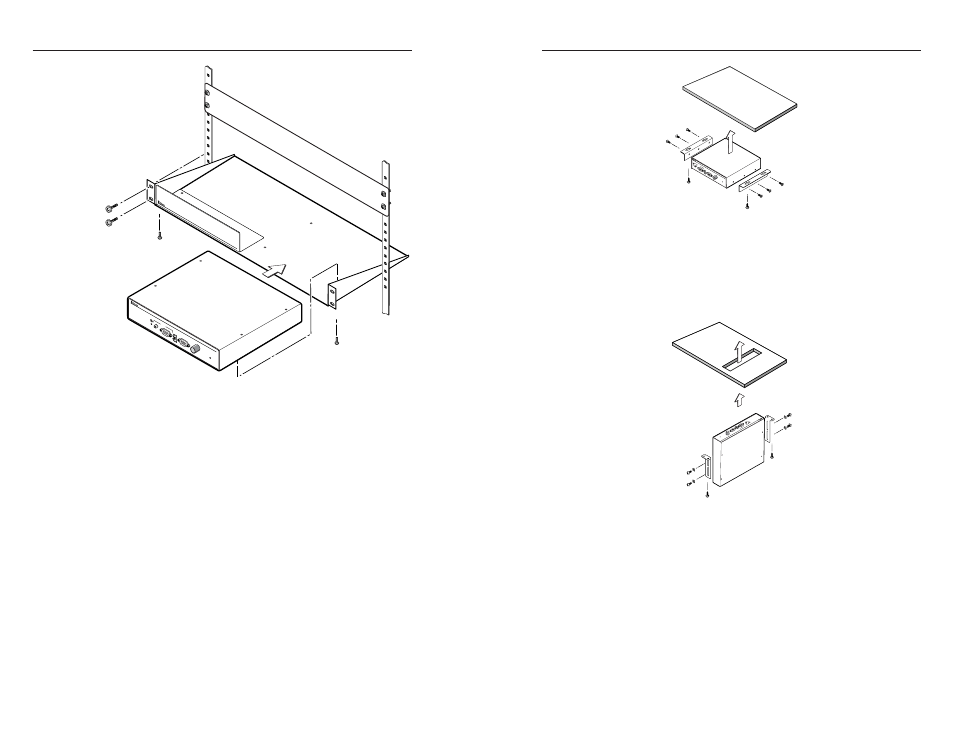
Figure 2-9 — Rack mounting the RGB 164xi
3
.
Install a blank panel (included in the rack kit) or another
1U half-rack unit on the unused side of the rack.
Under desk mounting
Mount the interface under a desk or in a podium as follows:
1
.
Attach the mounting brackets to the interface using six
machine screws supplied with the mounting kit
(figure 2-10).
2
.
Using the to-scale template at the back of this manual to
guide you, mark the four screw holes on the underside of
the surface to which you are mounting the interface. Use
the under desk mounting template.
3
.
Drill four pilot holes, each 3/32” in diameter by 1/4”
deep, where marked.
4
.
Using the four wood screws provided, attach the brackets
under the mounting surface.
RGB 160
INP
UT
RG
B 16
0 xi
UN
IVE
RSA
L IN
TER
FAC
E W
/AD
SP
H. S
HIF
T
ID
P
IN
4
ID
P
IN
1
1
AUDIO
Figure 2-10 — Attaching the under desk brackets
Through desk mounting
Mount the interface through a desk or table, as follows:
1
.
Attach the mounting brackets to the interface using four
machine screws and washers (supplied with the mounting
kit), as indicated in figure 2-11.
RGB 164
IN
PUT
RG
B 16
4 xi
UNIV
ERS
AL I
NTE
RFA
CE
W /A
DSP
H. S
HIF
T
ID P
IN 4
ID PIN 1
1
AU
DIO
Figure 2-11 — Attaching the through desk
brackets
2
.
Using the to-scale template at the back of this manual to
guide you, mark the four screw holes on the underside of
the surface to which you are mounting the interface. Use
the through desk mounting template to cut the hole.
3
.
Drill four pilot holes, each 3/32” in diameter by 1/4”
deep, where marked.
4
.
Using the four wood screws provided, attach the brackets
to the mounting surface.
2-7