Controls and installation, cont’d – Extron Electronics RGB 164xi User Guide User Manual
Page 11
RGB 130xi
xi
xi
xi
xi, 134xi
xi
xi
xi
xi, 160xi
xi
xi
xi
xi, 164xi
xi
xi
xi
xi • Controls and Installation
RGB 130xi
xi
xi
xi
xi, 134xi
xi
xi
xi
xi, 160xi
xi
xi
xi
xi, 164xi
xi
xi
xi
xi • Controls and Installation
Controls and Installation, cont’d
2-12
Off
— If this switch is set to Off, the interface performs
sync processing operations, such as horizontal
shift, using Extron’s ADSP™.
Turning on the DDSP feature disables the horizontal
shift control and the vertical shift control.
SERR (serration pulses)
Many display devices, such as LCD and DLP projectors and
plasma displays, must not have serration pulses present in the
sync signal in order to display images properly. Flagging or
bending at the top of the video image is a sign that the serration
pulses should not be present.
On
— When this switch is set On, serration pulses are
present with sync signal output.
Off
— When this switch is set Off, serration pulses are not
present with sync signal output.
75 Ohm (local monitor video input termination)
On
— Set this switch on for 75-ohm input termination.
Off
— Set this switch off for high impedance input
termination.
RGB 160xi and RGB 164xi only
The RGB 160xi and RGB 164xi have two pin termination DIP
switches to provide proper ID bit termination for a laptop
computer that is not attached to a local monitor.
ID PIN 4 & ID PIN 11
On
— Set both pins to On if you are using the RGB 160xi
or RGB 164xi interface with a laptop computer that
is not connected to a local monitor.
Off
— Set both pins to Off if you are connecting a local
monitor to the interface.
Setting internal jumpers
The jumpers inside the interfaces are set at the factory for
optimal use by most systems. However, you can change a
jumper setting to meet the needs of a particular system.
Changes to internal jumper settings must be
performed by authorized service personnel only.
The user-configurable, internal jumpers control the following
functions:
• Horizontal and vertical sync polarity
• Vertical sync pulse width
Follow these steps to change the jumper settings. The RGB
134xi is shown for illustration, but the steps apply to all
interfaces.
1
.
Remove power from the interface by disconnecting the AC
power cord from the unit.
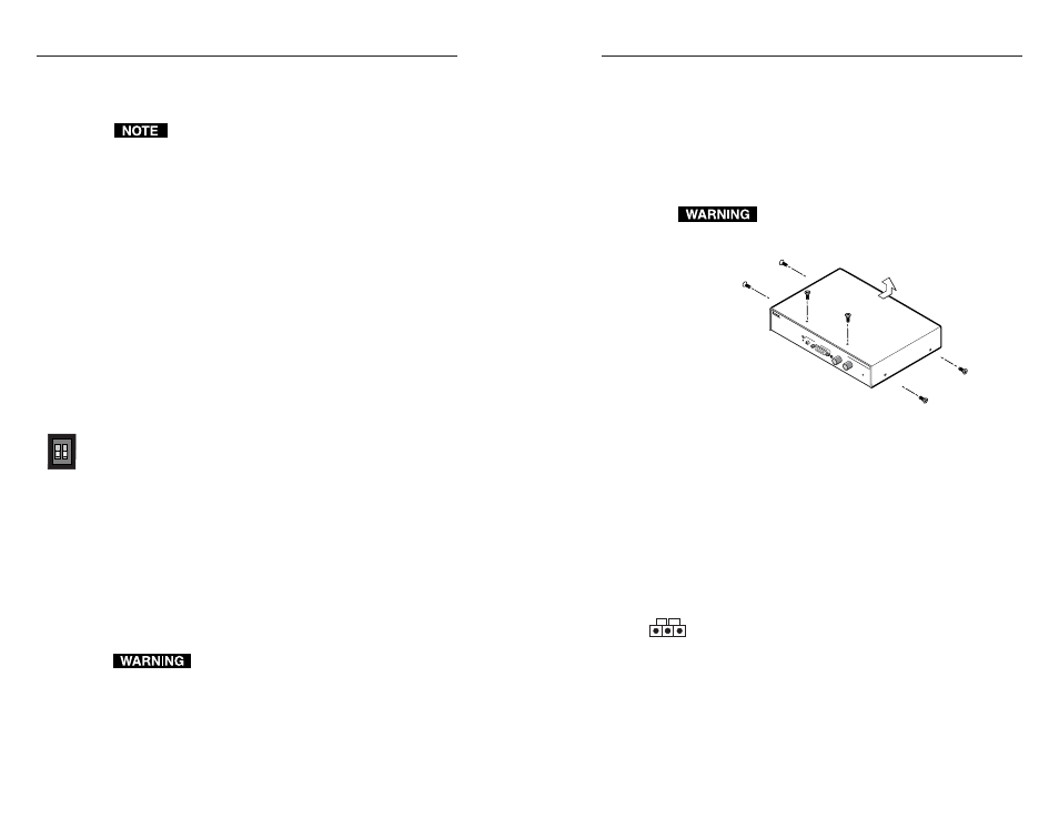
2
.
Open the cover of the interface (the top half of the
enclosure) (figure 2-18). Remove the screws from the
enclosure, and lift the cover straight up.
Do not touch any switches or electronic components
inside the interface. Doing so could damage the
interface.
Remove (6)
Screws
Slide cover back slightly,
lift straight up.
INP
UT
H. S
HIF
T
RG
B 13
4 xi
UN
IVE
RSA
L IN
TER
FAC
E W
/AD
SP
H. S
HIF
T
MIN
/MA
X
M
BC
PO
W
ER
AU
DIO
Figure 2-18 — Opening the interface cover
3
.
Note the positions of jumpers J20 and J40 before changing
jumper settings. Figure 2-19 shows the locations of the J20
and J40 jumpers and the two possible setting combinations
for 3-pin jumpers.
4
.
Configure the jumpers as defined below. To configure the
jumpers, use pliers to pull the jumper shunt off the pins,
then place the jumper on the appropriate pins
(figure 2-20).
The jumpers perform the following functions:
J20: Sync polarity jumper
— This jumper adjusts the output
sync polarity. Horizontal (H) and vertical (V) sync output
can either follow input sync polarity, or be forced to
negative.
•
If the jumper is placed on pins 1 and 2, output H and V
sync polarities is forced to negative.
•
If the jumper is placed on pins 2 and 3, output sync
polarity follows input sync polarity; the output sync
signal’s polarity is the same as the input polarity. This is
the default setting.
ID PIN 4
ID PIN 11
Negative
Follow
1
2-13