Rear panel installation features, Installation, Listed 1t23 i.t.e – Extron Electronics MAV Plus series Large Scale Setup Guide User Manual
Page 8: Crosspoint / mav matrix switchers • installation, Figure 2-1 — sync or video bme, Figure 2-2 — audio bme
CrossPoint / MAV Matrix Switchers • Installation
Installation
CrossPoint / MAV Matrix Switchers • Installation
2-2
Refer also to the CrossPoint 450 Plus / MAV Plus User’s Manual at
www.extron.com
.
2-3
Refer also to the CrossPoint 450 Plus / MAV Plus User’s Manual at
www.extron.com
.
4
8
3
7
2
6
1
5
LAN
ACT LINK
RESET
REMOTE
Rx
Tx
2A MAX
LISTED
1T23
I.T.E.
C
U S
12
16
11
15
10
14
9
13
OUTPUTS 1 - 16
20
24
19
23
18
22
17
21
28
32
27
31
26
30
25
29
OUTPUTS 17 - 32
36
40
35
39
34
38
33
37
44
48
43
47
42
46
41
45
OUTPUTS 33 - 48
52
56
51
55
50
54
49
53
60
64
59
63
58
62
57
61
OUTPUTS 49 - 64
4
3
2
1
8
7
6
5
12
11
10
9
16
15
14
13
20
19
18
17
24
23
22
21
28
27
26
25
32
31
30
29
36
35
34
33
40
39
38
37
44
43
42
41
48
47
46
45
52
51
50
49
56
55
54
53
60
59
58
57
64
63
62
61
Rx
Tx
4
-
+
BME COMM
IN
OUT
BME
ADDRESS
EXT
SYNC
INPUTS
75
510
1 2 3 4 5 6 7 8
75
510
9 11 13 15
10 12 14 16
ANAHEIM, CA
Rx
Tx
RESET
* Sync BME only
●
MAV Plus video BME only
1
2
10
4
9
2
11
8
7
3
*
*
●
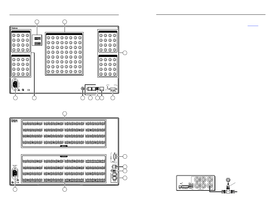
Figure 2-1 — Sync or video BME
C
11
7
8
9
6
10
5
Figure 2-2 —
Audio BME
N
Extron recommends locking redundant front panel
controllers (if included in your system). See page 3-4.
Rear Panel Installation Features
N
Only sync BMEs have sync termination switches.
Only MAV Plus video BMEs have External Sync connectors.
N
Smaller matrix sizes have fewer input connectors, output
connectors, or both.
Video and audio connections, sync termination,
and external sync
C
Turn off power to the input and output devices, and
disconnect their power cords.
a
Video inputs — Connect RGBHV, RGBS, RGsB, RsGsBs,
component/ HDTV video, S-video, or composite video sources,
as appropriate to your switcher system's video format and
matrix size.
b
Video outputs — Connect RGBHV, RGBS, RGsB, RsGsBs,
component/HDTV video, S-video, or composite video displays,
as appropriate to your switcher system's video format and
matrix size.
c
Sync termination switches (sync BMEs only) — Set the switches
as necessary to condition non-TTL sync levels greater than 5 Vp-p
for inputs 1 through 16 only
. Sync termination enables the sync to
be properly passed from an input to the selected output(s).
510 ohms —
The default position, suitable for most video.
75 ohms —
Typically required only for an input with non-TTL
sync (greater than 5 V p-p).
N
An input that produces an out of sync display, a display
that is rolling vertically and/or tearing horizontally, could
indicate a non-TTL sync input. If you are not sure, check
the specifications in the user’s manual for the input device.
d
External Sync (MAV Plus video BME) — If desired, attach an
external sync timing device to the external sync connector.
EXT
SYNC
POWER
12V
0.5A MAX
L
R
1
4
3
2
1
6
5
PAL
NTSC
BLACKBURST
BLACKBURST/
COLORBAR
-10dBV
+4dBu
1 2 3
ON
1 KHZ AUDIO
BBG 6 A
BLACK BURST/COLOR BAR
/AUDIO GENERATOR
Terminate cable
or connect to
another device.
Connect to
MAV Plus.
OUT
Extron BBG 6 A
Black Burst Color Bar
Audio Generator