System controller, Connect the display to the system controller, Connect the system controller to the switcher – Extron Electronics TeamWork Installation User Manual
Page 6: Connect power, Teamwork • installation guide (continued)
TeamWork • Installation Guide (Continued)
6
System Controller
The display and switcher in your system may be controlled by RS-232, Ethernet, or IR, depending on the models. The IPLink
control processor must be configured to communicate correctly with the display and switcher. See the user guide for the
controller for complete instructions about configuration. The guid
.
Connect the Display to the System Controller
Before connecting the controller to the display, see the user guide for that device. The guide is available at
.
ATTENTION:
If you are using the IPL T PC1i (International TeamWork kits) you must replace the power plug on the display
with the provided adapter (see
IEC C14 Male Power Cord Plug Installation
Connect the System Controller to the Switcher
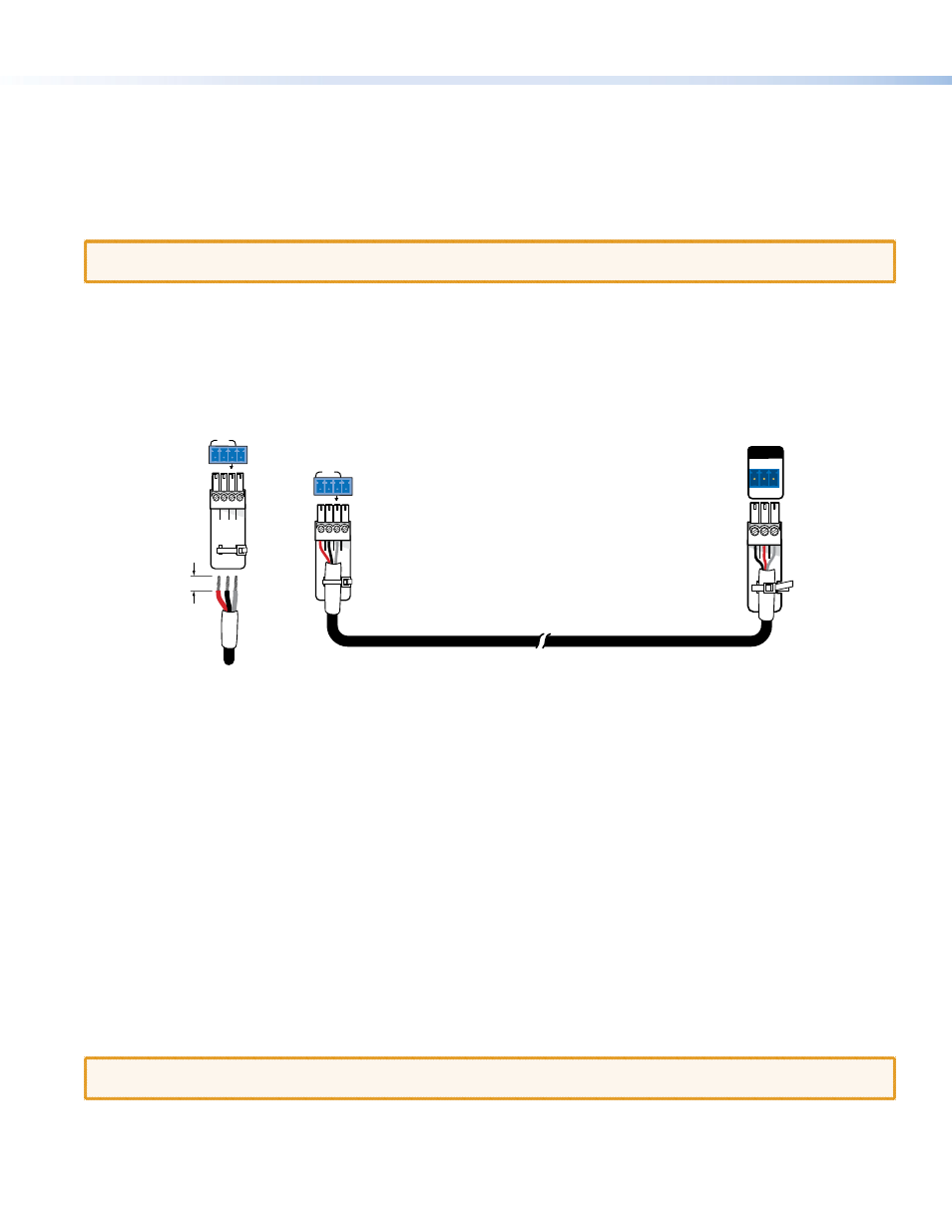
To connect the system controller to the switcher, you may need to make your own control cable.
The required captive screw connector is provided with each unit. The exact size (3-pole, 4-pole, or 5-pole) depends on the unit.
Although the number of wires that the connector can take varies, only three poles are required in each case: Tx, Rx, and ground.
In the figure below, the 4-pole COM port of the IPL T PC1 controller connects to the 3-pole RS-232 port of the MPS 601 switcher.
3/16" (5 mm)
Max.
COM
TX
+5V
RX
4-pole connector
(to system controller)
System Controller
(IPL T PC1)
COM
TX
+5V
RX
Switcher
(MPS 601)
3-pole connector
(to switcher)
4-pole connector
(to system controller)
Switcher Control Cable
RS-232
Tx Rx G
REMOTE
To make a control cable:
1.
Strip the outer sheath from each end of the control cable to expose about 1 inch of the three wires.
2.
Strip 3/16 inch of the sheath from each individual wire.
3.
On the captive screw connector provided with the controller, identify which pins correspond to Tx, Rx, and ground on the
controller COM port.
4.
Connect the three wires from one end of the control cable to the Tx, Rx, and ground pins of the captive screw connector.
5.
On the captive screw connector provided with the switcher, identify which pins correspond to Tx, Rx, and ground on the
RS-232 port of the switcher.
6.
Connect the three wires from the other end of the control cable as follows:
z
Controller Tx connects to switcher Rx
z
Controller Rx connects to switcher Tx
z
Controller ground connects to switcher ground
7.
Secure the control cable to the captive screw connectors at both ends using the cable tie provided.
Connect Power
If the device has an internal power supply, connect the power cord to a wall outlet.
If the device requires a power supply, connect the power supply provided to the device.
ATTENTION:
Do not connect any external power supplies until you have read the Attention notifications in the “Power
Supply” section of the user guide for that device.