Mounting the tlp 350cv and tle 350, Step 1 - obtain cut-out dimensions, Step 2 - cut the surface – Extron Electronics TLE 350 Setup Guide User Manual
Page 2: Step 1 — obtain cut-out dimensions, Step 2 — cut the surface, Caution, Attention, Downloads
2
TLP 350CV and TLE 350 • Setup Guide (Continued)
2
Mounting the TLP 350CV and TLE 350
Step 1 — Obtain Cut-out Dimensions
ATTENTION:
•
The table should be cut only by licensed and bonded craftspeople.
•
Make certain the correct cut-out dimensions are being used before proceeding to the next step. Extron is not
responsible for mounting holes that are incorrectly cut.
•
The surfaces of the Cable Cubby enclosure have screws and other protruding hardware that could damage fine
furniture. Do not rest the enclosure on unprotected furniture.
•
Ensure the table surface is at least 0.375 inches (0.95 cm) thick.
z
If using a hand router, you should purchase the Extron TLP 350CV routing template (part number
70-694-01).
z
If using a CNC wood router, use the exact cut-out dimensions (see below).
z
If using a reciprocating saw or jigsaw use the paper cut-out template (part number
68-2148-01, available under the
Downloads
.)
Step 2 — Cut the Surface
CAUTION:
Risk of personal injury: To avoid eye injury, wear safety glasses when operating power equipment.
Be certain the cut is laid out in exactly the desired location and the edge that opens on the lid is correctly oriented. After verifying
and checking dimensions, cut a hole in the surface of the furniture where the enclosure will be installed (see “Preparing the Table”
in the TLP 350CV User Guide). There are three methods for cutting the hole in the table:
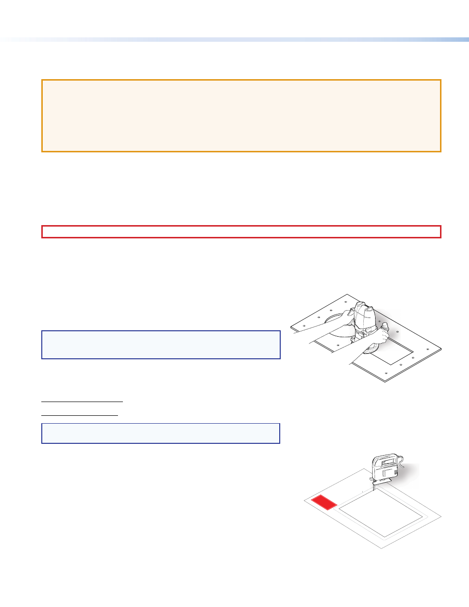
Using a hand router
Recommended method — Use the Extron TLP 350CV routing template, part
number
70-694-01. Refer to the Routing Template User Guide, available at
to prepare the template and use the template to cut the
hole.
NOTE:
The metal router guide must be purchased separately. It
is reusable and should not be discarded when the installation is
complete.
Using a CNC wood cutter
Recommended method — Use the exact cut-out dimensions:
7.50 +0.00/-0.02 inches W x 6.00 +0.00/-0.02 inches D
(19.05 +0.00/-0.05 cm W x 15.24 +0.00/-0.05 cm D)
NOTE:
The underlined dimension is the connector or AAP access side
for the unit.
Using a reciprocating saw or jigsaw
Acceptable method — Use the paper cut-out template (part number 68-2148-01,
available under the
Downloads
tab on the TLP 350CV page at
HSA 200
USER A
CCESS
HSA 200
CABLE C
UBBY 30
0
CABLE
CUBBY
300
USER A
CCESS
Cut-Out
Template
for the Extron
TLP 710C
V
Outer E
dge of
Trim Ring
(Do no
t cut th
is lin
e.)
1.
Conf
irm th
e pr
oduct
to be
instal
led.
2.
Remo
ve the
surf
ace c
ut-ou
t are
a
(g
ray) fr
om th
e tem
plate
.
3.
Mark
the po
sition
on th
e wa
ll o
r
furn
iture
where
the
TLP 7
10M
V
is be
ing in
stal
led.
4. Cu
t the
opening.
P/N 6
8-2046
-01
Rev
. B
Pag
e s
ize
: 11" x 17
"
Print scale 1
:1
Do not shrink
.
P/N
P/