Extron Electronics FOX 3G HD-SDI User Guide User Manual
Page 25
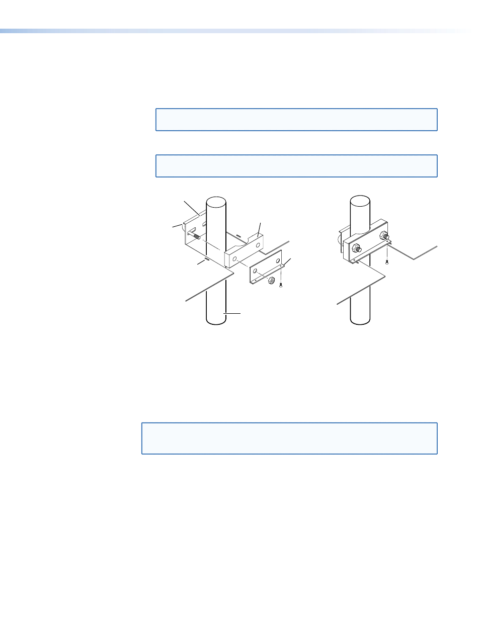
6.
Assemble the U-bolt and the following parts in the following order (figure 14):
a.
Pass the legs of the U-bolt through the slotted holes on the mount plate flange.
b.
Place the legs around the projector pole.
c.
Pass the legs through the holes in the contour base.
NOTE: The pole fits snugly into the depression in the center of the contoured
base.
d.
Pass the legs through the holes in the L-shaped bracket.
NOTE: The supplied U-bolt fits a typical (1.5-inch to 2.0-inch diameter) ceiling
pole.
U-bolt
Slotted Hole
in PMK Tray
L-shaped
Bracket
L-shaped
Bracket Screws
Contoured
Base
Ceiling
Pole
Mount Plate
Flange
Figure 14.
Hanging the Tray on the Pole
7.
Align the two slotted holes in the bottom of the L-shaped bracket with the two slotted
holes in the base of the tray. Secure the L-shaped bracket to the base by inserting two
provided 6-32 x 5/16-inch screws through the aligned slots.
8.
Move the PMK 350 up to the desired location on the ceiling pole, as close to the ceiling
as desired.
9.
Secure the L-shaped bracket to the U-bolt using the included hex nuts, washers, and
lock washers. Tighten the hex nuts securely.
NOTE: Be sure to tighten the hex nuts securely enough so that the PMK 350 does
not slide down the ceiling pole. A socket wrench is recommended to tighten
the hex nuts.
10.
Secure the front and rear plates to the mounting tray with four of the included #6
screws.
11.
If desired for aesthetics, choose one of the provided four sizes of self-adhesive cover
sheets that most closely resembles the surrounding ceiling material, and apply it to the
underside of the mounting tray.
FOX 3G HD-SDI • Reference Information
21