Serial communications, cont’d, Command/response table for programming the ctl208 – Extron Electronics CTL208CM User Manual
Page 21
CTL208CM Control Panel Module • Serial Communications
CTL208CM Control Panel Module • Serial Communications
Serial Communications, cont’d
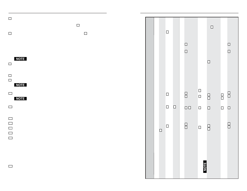
Command/response table for programming the CTL208
C
o
m
m
a
n
d
ASCII Command
Response
Additional description
(host to CTL208)
(CTL208 to host)
Addressing
Connect
[C
C
X1
]
{none}
Connect the host computer to the addressed
unit. This command is case sensitive.
Specify address number
[A
D
D
R
X1
]
[R0•
X1
•ADDR
X1
•
]
Change the CTL208’s address to
X1
.
Example:
[ADDR95]
[R0•95•ADDR95•]
Change the address number to 95.
Reset address to factory default
[ADDR@]
[R0•
X1
•ADDR@•]
Reset the CTL208’s address to the factory
default (97).
Button code programming
Store ASCII code to a button
[PCLp
X2
X3
]
R0•
X1
•PCLp
X2
X3
•
]
Program button
X2
to
X3
.
Example
:
[PCLp02’CH3”
R
0
•
X1
•PCLp02’CH3”•]
Programs button 2’s primary code to send the
command string [CH3]. The ’
and ”
characters insert the delimiter brackets.
V
iew a button’s
ASCII code
[PCLp
X2
?]
R0•
X1
•PCLp
X2
?•
X3
]
Brackets inserted using the insert brackets feature appear as brackets when you use view command.
Set an insert brackets character
[BKT
X4
X5
]
R0•
X1
•BKT
X4
X5
•
]
Set the
X5
character as the insert brackets
character for the left or right bracket (
X4
).
Example
:
[BKT1’]
R0•97•BKT1’]
Set the single quote ( ‘ ) character as the insert
brackets character for the left bracket.
V
iew insert brackets characters
[BKT?]
R
0
•
X1
•BKT
X5
X5
•
]
The replacement characters are listed in the
order {left}{right}.
Store hex code to a button
[P
C
H
p
X2
X6
]
R0•
X1
•PCHp
X2
X6
•
]
Program button
X2
to
X6
.
Example
:
[PCHp030F
R0•97•PCHp030F•]
Programs button 3’s primary code to send the
hex command string 0F.
X5
=
Bracket character
0 = turn off insert bracket feature. Any character
other than 0 is the character that will be replaced by
a bracket ( [ or ] ) when the
X3
code is saved to a
CTL208 button.
X6
=
Hex button code
Similar to the ASCII button code,
X3
, with the
addition of an ASCII-to-hex conversion before the
value is stored. For example, if you send the ASCII
value 0F, the CTL converts it to the hex value 0F.
When you press the button, the CTL sends 0F hex.
Entries must be in pairs, use a leading 0 if necessary.
Letters must be upper case.
The insert brackets feature does not work for hex codes.
X7
=
Button mode
0 = Single mode
1 = Toggle mode
2 = Press/release
3 = Continuous
X8
=
Button group number
1 or 2
X9
=
Button group assignment
0 = Not assigned, 1 = Assigned
Groups cannot be assigned to buttons that are set to operate in
timeout mode.
X10
= Button timeout interval
0 or 1 - 255 (minutes). 0 = no timeout.
Timeouts cannot be assigned to buttons that are set to operate in
groups.
X11
= Baud rate
0 = 1200
1 = 2400
2 = 4800
3 = 9600 (default)
4 = 19,200
5 = 38,400
X12
= Parity mode: 0 = no parity (default), 1 = odd parity, 2 = even parity
X13
= Flow control mode: 0 = Xoff (default), 1 = Xon
X14
= Duplex mode: 0 = full duplex, 1 = half duplex (default)
X15
= Front panel and responses: 0 = disable, 1 = enable (default)
X16
= Reset level: 0 = reset the serial port to 9600 baud, no parity, Xoff, and
half duplex mode; reset the address to 97; and enable
the front panel.
1 = perform all of the same resets AND erase all button
codes, reset all buttons to single mode, and reset all
button groups and timeouts to 0. This reset is identical
to the DIP switch reset, see Factory Reset in chapter 3,
Operation.
X17
= Architectural information:
C208•{serial #}•{Rev level}•{firmware #}•{firmware Rev level}•{available
baud rates}1200,2400,4800,9600,19200,38400•{2 bytes for future use}
4-12
4-13