Extron Electronics CIA112 User Manual
Page 6
4
CIA112 Operation Manual - V1.3 01/31/01
©2001 - INLINE, Inc.
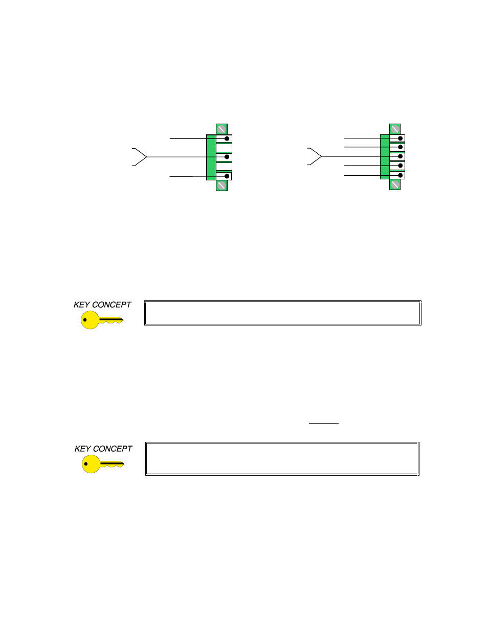
6. Connect the Audio Cable to the appropriate pins on the CIA112 5-pin Phoenix connector.
Make sure that the stereo audio output is connected appropriately for unbalanced or balanced
as required by the installation (see diagram below).
Unbalanced Output - connect to the Left, Right and Ground connectors.
Balanced Output - connect to Left +, Left-, Right+, Right- and Ground connectors.
5LJKW *URXQG
/HIW *URXQG
/HIW
5LJKW
8Q
EDO
DQ
FH
G
%D
OD
QF
HG
5LJKW *URXQG
/HIW *URXQG
/HIW
5LJKW
5LJKW
/HIW
7. If the Application Requires Remote Switching Capability, connect the remote control
cables to the 3-pin Phoenix connector on the back of the CIA112. The connector works with
any device that provides latching contact closure such as a third party control system or the
IN9360 Contact Closure Switch module (optional). Each time the remote connector circuit is
opened or closed, the CIA112 will select the opposite input. This could be either Input 1 or
Input 2, depending on the current position of the front panel switch. The CIA112 remote
connector has a status pin that can provide feedback to a control system or remote button to
indicate which input is currently selected. When the status pin is low, this indicates that Input
1 is currently selected. If the status pin is high, Input 2 is selected.
Note: Remote switching is only functional when autoswitch is disabled (see
the Dipswitch Settings Section on page 9).
8. Apply Power to the CIA112 using the
IN9213 / IN9222 9 VDC; 1.5A
power supply
(included). The CIA112 power connector (2-pin captive screw terminal) has a sticker
showing the correct polarity. Be extra careful to connect the power supply positive wire
(with the red heat shrink) to the interface power connector’s (+) terminal, and the power
supply negative wire to the interface power connector’s (-) terminal. Connecting the
power with the reverse polarity may permanently damage the unit! If in doubt, measure
the power cable with a voltmeter to verify the positive and negative terminals.
Note: Unlike other CIA Installation Series Interfaces, the CIA112 does not feature auto power
ON/OFF capability. Once power has been applied, the unit stays ON at all times.
When extending AC cable for distances of 50’ or more, use an 18-gauge to
22-gauge power cable (thinner cables may cause problems). The INLINE
IN8500-2P power cable is well suited for this application.
9. Turn the Computer and Computer Monitor Off. Disconnect the monitor (if present) from
the video output port on the computer.
10. Connect the Computer Graphics Card to the CIA112 15-pin video input port.
•
PC / MAC / SGI Computers with 15-pin HD Video Ports - can be connected via
IN8000M-1 / IN8200M-1 Series high-resolution coaxial VGA cables.
•
Older Macintosh (15-pin D) / SUN (13W3) / Workstations (4 or 5 BNC) - can be
connected using the appropriate input / output cables listed below.