Preparing the cable cubby, Step 1 — assemble connectivity modules – Extron Electronics Cable Cubby 1400 User Manual
Page 3
3
Preparing the Cable Cubby
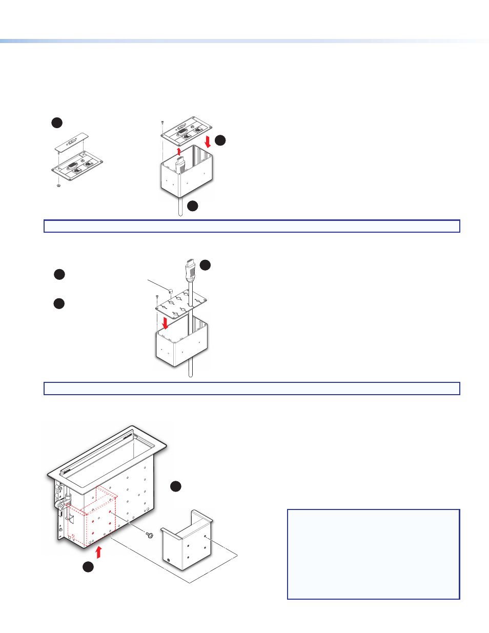
Step 1 — Assemble Connectivity Modules.
Connectivity modules allow you to populate the Cable Cubby enclosure with a combination of AAPs, cable pass-through, or
retractors. Follow the steps below to assemble the connectivity modules of your choice.
Option 1: AAP Module
Option 2: Cable Pass-Through Module
Option 3: Retractor Bracket
NOTE:
After assembling the module, proceed to
NOTE:
After assembling the module, proceed to
on the next page.
NOTE:
•
Use a screwdriver to secure the Retractor
bracket with the screws.
•
After installing the bracket, proceed to
on the
next page to install the power module.
•
Install the Retractors after the Cable Cubby
is mounted on the table (see
on page 5).
Secure up to three single-space
AAPs in the AAP plate.
Secure the AAP plate on the connectivity brackets,
using four of the provided module screws.
#4-40 Nut with
Captive Washer
Insert cables through the bottom of the connectivity bracket.
Connect cables to the AAPs.
Insert cables through the bottom of the connectivity bracket
and into the holes of the grommet plate.
Secure the grommet plate on the
connectivity bracket, using four
of the provided module screws.
Snap the included hole plugs into
any unused holes.
1
3
2
1
2
3
Secure the bracket using four of the
provided mounting screws with star washers.
Insert the bracket
into the Cable Cubby.
S
p
The bracket may be installed
on the left or right side of the
enclosure and at the lowest height.
2
1