System 5000™ hardware – Xylem System 5000 Getting Started Guide User Manual
Page 20
Serial Port Pin-Out
PIN DIRECTION
NAME
1
Input
Data Carrier Detect
(DCD)
2
Input
Receive Data
(RD)
3
Output
Transmit Data
(TD)
4
Output
Data Terminal Ready
(DTR)
5
N/A
Ground
(GND)
6
Input
Data Set Ready
(DSR)
7
Output
Request To Send
(RTS)
8
Input
Clear To Send
(CTS)
9
Input
Ring Indicator
(RI)
18
SYSTEM 5000™ HARDWARE
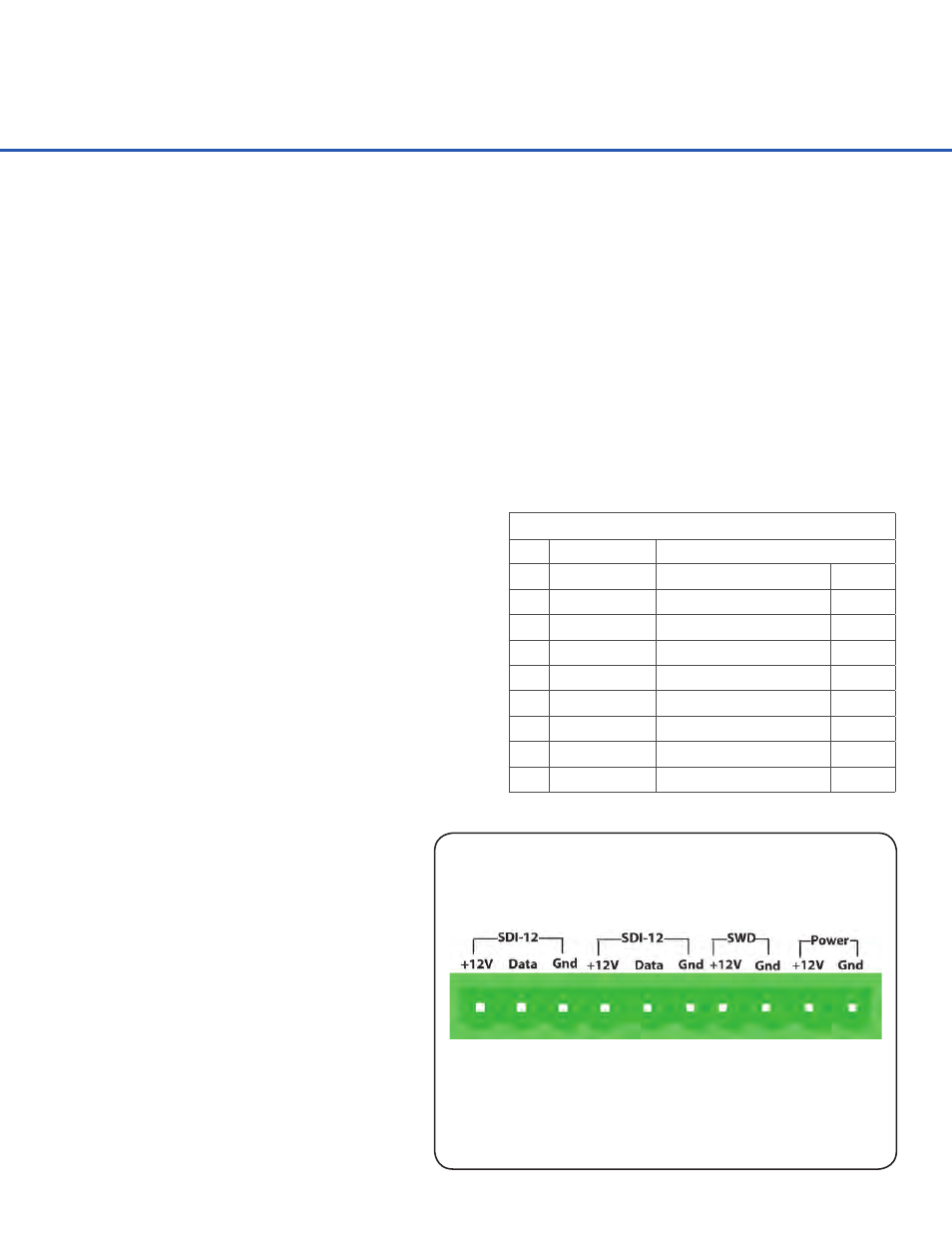
The SDI-12 Ports are provided to
connect SDI-12 compatible sensors.
Standard SDI-12 sensors have a
minimum of three wires, which are
+12V, Data, and Gnd. There are two
SDI-12 ports, as shown above, for ease
of connecting multiple SDI-12 sensors.
SDI-12 Ports
The two USB-A connectors are provided to connect an external USB “Device”, like a USB Flash
drive, for downloading or uploading data to the System 5000™ internal memory. The USB-B
connector is provided to allow a direct connection from the System 5000™ to a computer for
downloading or uploading data and in this case, the System 5000™ is seen as a USB “Device”,
showing up as an external hard disk on the connected computer.
USB Ports
The Ethernet port is a 10/100 BaseT port allowing the System 5000™ to connect to a Local Area
Network or to a Wide Area Network (Internet). Remote operation, System 5000™ programming,
and ports listening for incoming connections (e.g. simple web pages) can all be done through
this port.
Ethernet Port
The two RS-232 ports are provided to connect
to a PC, GOES Transmitter, modem, remote
display, or other standard serial communication
equipment. These ports are configured as a DTE
type of device. This means they will plug directly
into a modem (DCE type device), but will require
a NULL modem adaptor and gender changer if
connected to a PC (DTE type device). The NULL
modem cable crosses the communication lines
allowing two similar devices to communicate.
The pin out for the RS-232 ports is shown to the
right.
RS-232 Ports