Bell & Gossett P86272B VS Variable Speed Pump Control User Manual
Page 7
7
INITIAL SETTINGS FOR A RESET CONTROL
(see r on pg. 6)
• After setting the operating mode, the VS will display the tem-
perature of the Secondary loop. This is the default display.
• To see and/or adjust the other parameters, press then
release the center button marked PRESS TO READ. The VS
will display a code to indicate which parameter will be
displayed next. After two seconds, the value of the
parameter will be shown.
• For those parameters where the values can be set (shown
on chart pg. 8), press the UP or DOWN button to change
the value while it is being displayed. Holding the UP or
DOWN button will cause the value to change more quickly.
• The Outdoor Cutoff (COF ), also known as warm weather
shut down, temperature setting is the outdoor temperature
above which the VS will not give heat. The factory default
setting is 60°F.
• The Reset Ratio (rSt ) determines how quickly the water
temperature in the Secondary loop will increase as the
outdoor temperature decreases (see Figure 6). Lower
numbered curves result in lower water temperatures. The
factory default curve is 7 or (1:1). This means for every
degree the outdoor temperature falls (below the System
Start temperature) the Secondary loop temperature will be
increased by one degree. For baseboard heat, start with 7.
For most radiant tubing applications, start with 4 and an
offset of -10 (see page 10).
• The Offset (OFS ) value is added or subtracted to the
calculated water temperature for the Secondary loop. It
effectively moves the starting point of the reset curves up
and down by the number of degrees selected (see pg. 10).
Start with the factory default setting of 0.
• The Low Return (LOr ) comes factory set to OFF. This is the
correct setting if you are not using the Boiler return water
sensor. If you do use the Boiler return sensor for boiler
protection, then the setting must be set to the boiler
manufacturer’s specification.
• The High Supply (HI ) value must be adjusted to the
maximum temperature value specified for the Secondary
loop components.
• The Setback (Sbc) value determines how many degrees the
Secondary loop temperature will be decreased when the
EXT Input in the Setback mode (see pg. 11) is shorted. Start
with the factory default setting of 10°F. In order to adjust
the setback value, Sb has to be selected in the initial
operating mode sequence. If tt is selected, the setback Sbc
will be OFF.
INITIAL SETTINGS FOR A SET POINT CONTROL
(see S on pg. 6)
• After setting the operating mode, the VS will display the
temperature of the Secondary loop. This is the default value
for the VS display.
• To see and/or adjust the other parameters, press then
release the center button marked PRESS TO READ. The VS
will display a code to indicate which parameter will be
displayed next. After two seconds, the value of the
parameter will be shown.
• For those parameters where the values can be set (shown
on chart pg. 8), press the UP or DOWN button to change
the value while it is being displayed. Holding the UP or
DOWN button will cause the value to change more quickly.
• The Outdoor Cutoff (COF ), also known as warm weather
shut down, temperature setting is the outdoor temperature
above which the VS will not give heat. Set to ON if the
system set point should be held regardless of outside
temperature. The factory default setting is 60°F.
• The Low Return (LOr ) comes factory set to OFF. This is the
correct setting if you are not using the Boiler return water
sensor. If you do use the Boiler return sensor for boiler
protection, then the setting must be set to the boiler
manufacturer’s specification.
• The Set Point (SP ) should be set to the desired tempera-
ture for the Secondary loop.
• The Setback (Sbc ) value determines how many degrees the
Secondary loop temperature will be decreased when the
EXT Input in the Setback mode (see pg. 11) is shorted. Start
with the factory default setting of 10°F. In order to adjust
the setback value, Sb has to be selected in the initial
operating mode sequence. If tt is selected, the setback Sbc
will be OFF.
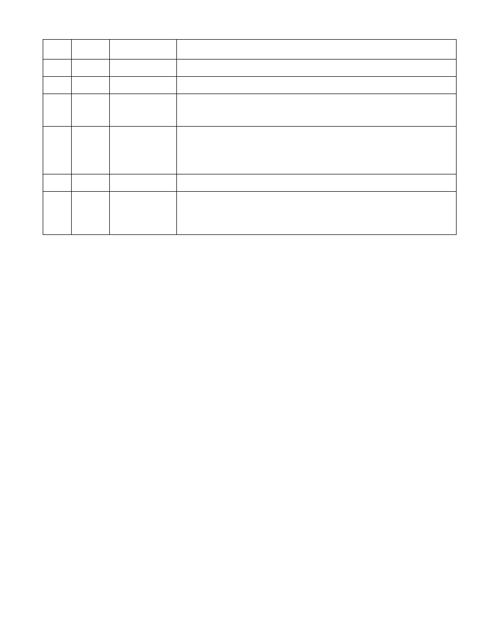
SEQ.
INITIAL FACTORY
NO.
DISPLAY
SETTING (DEFAULT)
MODE DESCRIPTION
1.
1
N/A
Software Version (no changes required)
2.
°F or °C
°F
Temperature in °F or °C that the VS will operate (°F is the initial default setting)
3.
r or s
r
Reset or Set Point Operation. r will run the VS as an outdoor reset control. As outdoor
temperature gets colder, the temperature in the secondary loop will automatically increase
(see page 10). s will run the VS so that the selected set point temperature is maintained in
the secondary loop. See chart on page 8 for instructions on setting the set point temperature.
4.
Sb or tt
tt
Setback or Thermostat. tt setting can be used with a thermostat, when thermostat has a call for
heat (input is closed) the injection and secondary pump are allowed to operate. When thermostat
is satisfied (input is open), the pumps will not operate (turn off). ss is used with an external NO
timer or clock. When input is closed, the temperature of the secondary loop will decrease by the
amount of the setback (Sbc). When input is open, the VS will go into Boost mode for 60 minutes.
After 60 minutes, the VS will return the secondary loop to the set point temperature.
5.
no or YES
YES
Pump Exercise. YES will activate both pumps for 10 seconds every 3 idle days
no, the pumps will only run when the system requires them to operate.
6.
nrS or rS
nrS
Boiler Return Sensor for Boiler Protection. nrS setting will not monitor the return water
temperature to the boiler. rS setting will monitor the boiler return water temperature. If the
return water drops below the Low Return Temperature (Lor ) setting, the speed of the injection
pump will be reduced by half the current speed until the Return Temperature rises above
the Minimum Return Temperature.
SETTING THE OPERATING MODE (IN SEQUENCE)