L o a d, Boiler, Piping – Bell & Gossett P86272B VS Variable Speed Pump Control User Manual
Page 4: Vs wiring diagram (fig. 3)
PIPING
PIPING OVERVIEW
• The Primary loop may have multiple injection loops or other
takeoffs. However, the piping for each injection system
must meet the requirements described below.
• The Injection piping can be installed in either a horizontal or
a vertical configuration.
• The pipe diameters of the Primary and Secondary loops
may differ.
• The Injection Piping diameter must be at least one pipe size
smaller than the smaller of the Primary and Secondary loop
piping. For example, if the Primary loop diameter is 1
1
/
4
"
and the Secondary loop diameter is 1", then the diameter of
the Injection piping must be
3
/
4
" or smaller.
• The Injection pump motor must be a fractional B&G NRF,
NBF or SSF permanent split capacitor type pump. (Refer to
operational limits on Page 2 for pump information.) The
Injection pump will control the amount of water pumped
from the Primary loop into the Secondary loop.
• A balancing valve should be installed on the injection return
piping. This helps to balance the system.
• The distance between the injection tees should be as short
as possible. The rule of thumb distance between the tees is
3 times the pipe diameter. For instance, if the pipe diameter
is 1" then the length of straight pipe between the two
injection tees should be 3".
HORIZONTAL PIPING CONFIGURATION
• The Injection piping can be installed horizontally as shown
in Fig. 2.
• The Injection supply piping should run horizontally from the
Primary to the Secondary loop.
• On the Injection piping it is necessary to install a heat trap
to prevent heat from the Primary loop entering the Secon-
dary loop when the Injection pump is not running.
• The injection piping must drop down vertically at least 18"
and then rise back up vertically at least 18".
VERTICAL PIPING CONFIGURATION
• The Injection piping can be installed vertically.
• The Primary loop must be at least 18" vertically above the
Secondary loop.
4
CAUTION: The Injection pump and pipe sizing
should be performed by a qualified engineer or
contractor.
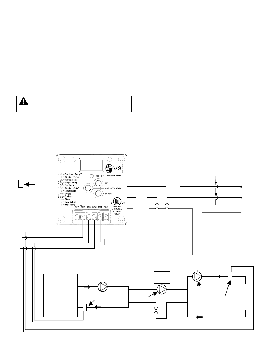
Secondary
Loop Sensor
Secondary
Loop Pump
Outdoor
Sensor
BLUE
RED
BLACK
120 VAC
LINE
NEU
Setback or
Remote Enable
L
O
A
D
Pump
Starter /
Motor
••
Pump
Motor
•
Injection
Pump
Boiler Return
Sensor
Boiler
•
•
Injection pump must be connected directly to 120VAC motor N.O. pump starter.
••
Secondary pump starter/motor can be 115V or 230V.
VS WIRING DIAGRAM (Fig. 3)
NOTE: Injection Pump and the VS Control MUST be
wired to the same power circuit. The secondary loop
pump can be wired to a different circuit if required.